
Directionally oriented piezoelectric materials and methods of fabrication

a piezoelectric material and directional orientation technology, applied in the direction of crystal growth process, crystal growth process, mechanical vibration separation, etc., can solve the problems of partial melting or mixing of materials, limited use of ultrasonic waves to weld metals, and difficult current techniques, etc., to achieve effective electrical shortening of transducers as they get thinner and thinner, and high frequency

Inactive Publication Date: 2018-01-04
BURGETT ERIC A
View PDF0 Cites 2 Cited by
  • Summary
  • Abstract
  • Description
  • Claims
  • Application Information

AI Technical Summary

Benefits of technology

This patent describes a method for creating directionally-oriented piezoelectric materials using chemical vapor-phase deposition (CVD) or physical vapor phase deposition (PVD) processes. These materials have innovative features that enhance their performance as ultrasonic transducers, with applications including underwater sonar devices, non-destructive testing devices, tank level indicators, eddy current detectors, ultrasonic wellfield characterization devices, and in-fluid imaging devices.

Problems solved by technology

This is especially true of advanced alloys, advanced ceramics, and advanced composites where the complexity of their makeup and the decreasing size of features and defects makes NDT very challenging using current techniques.
Ultrasonic waves can also be used to weld metals, but are typically limited to small welds of thin, malleable metals, e.g. aluminum, copper, nickel.
Difficulties in creating quality welds repeatedly and consistently stem from the use of lower than optimal frequencies that do not efficiently deposit the sonic energy precisely at the interfacial zone, causing only partial melting or mixing of the materials.
Making thin transducers is difficult.
One way to overcome both of these difficulties is through the use of single crystals or homogenously structured transducer materials but fabricating bulk single crystals has been difficult to accomplish.
This benefit of bi-directional orientation is not possible with omnidirectional piezoelectric materials.
A non-tunable crystal operated at non-resonant frequencies performs with poor efficiency, poor signal to noise ratios, and reduced operational lifetime of the transducer.

Method used


Image

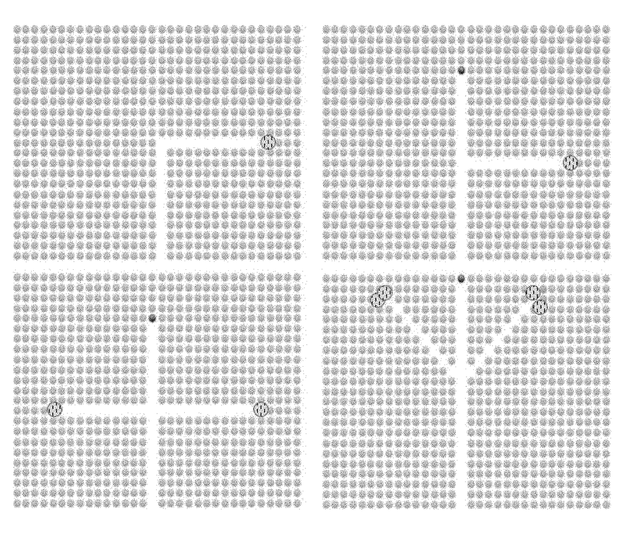
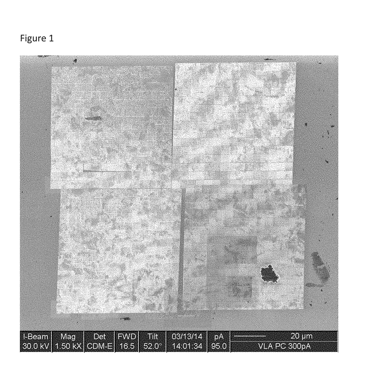
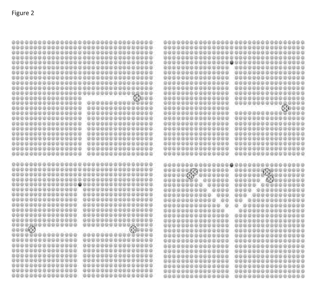
  • Directionally oriented piezoelectric materials and methods of fabrication
  • Directionally oriented piezoelectric materials and methods of fabrication
  • Directionally oriented piezoelectric materials and methods of fabrication

Examples


Embodiment Construction

[0034]Referring now to the drawings, the invention will be described in more detail.

[0035]1. Novel Piezoelectric Materials and Fabrication Method

[0036]Directionally-oriented piezoelectric materials are formed by using a chemical vapor deposition (CVD), or similar, process to grow very thin layers (i.e., nanometer-scale) of epitaxial ZnO in the wurtzite form with the c-plane preferentially oriented upward. This technique can also be used to fabricate directionally-oriented piezoelectric crystals with other, similar III-V and II-VI materials, as well as III-O and II-O materials such as: gallium oxide and other oxides including alloys and band gap engineered materials of III-V, III-O, II-O, and II-VI materials, as well as nitrides such as gallium nitride (GaN), indium nitride (InN), and aluminum nitride (AlN), boron nitride (BN), and alloys of these. The ZnO, or other material, would be deposited on a single-crystal substrate, for example, sapphire. Other potential substrate materials ...


PUM

PropertyMeasurementUnit
frequenciesaaaaaaaaaa

Abstract

Using a chemical vapor-phase deposition (CVD), physical vapor phase deposition (PVD) process or similar, novel directionally-oriented piezoelectric materials are created from zinc oxide (ZnO) and similar materials with innovative features that enhance their performance as ultrasonic transducers. Applications for these enhanced piezoelectric materials and transducers include: underwater sonar devices, non-destructive testing devices, tank level indicators, eddy current detectors, ultrasonic wellfield characterization devices, and in-fluid imaging devices (e.g., under-water and under-sodium viewing devices).

Description

BACKGROUND OF THE INVENTION[0001]The ultrasonic transducer described below is a device which makes different forms of physical waves with different shapes, amplitudes, frequencies and waveforms which can be repeating or arbitrary in nature. Their frequency is above that of the audible range for humans extending from 10s of kHz to the GHz and THz levels. These physical waves propagate through matter and produce different effects. They can produce heat, resonate solid, liquid and gas molecules, reflect and refract off different material interfaces, and get absorbed in materials among other things. These physical waves can be created unidirectionally in 3D space or omnidirectionally. In non-destructive testing, biomedical applications, and imaging applications, the ultrasound waves reflect and refract off of different material types, densities, and compositions. In pulse echo mode, these reflections are observed. In pulse transmission mode, the attenuation of the waves is observed as w...

Claims


Application Information

Patent Timeline
Patent Type & Authority Applications(United States)
IPC IPC(8): B06B1/06H01L41/187C30B29/68H01L41/253C30B25/02H10N30/04H10N30/853
CPCB06B1/0644H01L41/253H01L41/1873C30B25/02C30B29/68C30B29/16H10N30/079H10N30/706H10N30/708H10N30/04H10N30/8542
Inventor BURGETT, ERIC A.
Owner BURGETT ERIC A
Learn More