
Oriented Multilayer Porous Film

a multi-layer, porous film technology, applied in the direction of cell components, cell component details, electrochemical generators, etc., can solve the problems of poor heat resistance, creep and degradation, failure of the methods in creating a properly high level of open pores, etc., to enhance stress-induced hardening and orientation, improve the effect of ionic conductivity and excellent ionic conductivity

Pending Publication Date: 2018-02-15
LISO PLASTICS L L C
View PDF6 Cites 105 Cited by
  • Summary
  • Abstract
  • Description
  • Claims
  • Application Information

AI Technical Summary

Benefits of technology

The present invention provides a porous film that can be used as a separator in batteries and energy storage devices. The film has excellent ionic conductivity and electrical insulation properties. It is biaxially stretched to enhance stress-induced hardening and orientation, while thinning the gage to minimize materials consumption. The film has superior resistance to heat, solvents, puncture, and degradation under an electrochemical condition. It can effectively prevent the formation, growth, and penetration of Li or metal dendrites causing often the failure of the electrochemical cell. The film has multiple transitions, capable of serving simultaneously as a low shutdown and high meltdown temperature. The film is made out of biopolymers that have properties and cost, comparable to or better than corresponding petroleum-based polymers. The electrochemical cell comprising the film provides high power and energy densities, rate capability, safety, reliability, and a long life cycle. The present invention also provides a facile single-step method of manufacturing a porous film of a wide range of non-PO based high Tm or high glass transition temperature (Tg) polymers, compositions, and structures that are otherwise very difficult or impossible to produce commercially useful porous or separator film products.

Problems solved by technology

In the current state of the art, however, the dry and wet methods are limited primarily to production of polyolefin (PO)-based porous separator films.
This is due mainly to failure of the methods in creating a properly high level of open pores into non-PO based polymeric films.
The trade-offs are, however, a poor resistance to heat, creep and degradation; and a nonwettability to electrolytes under the cell condition.
The PO separator is thus susceptible to formation and penetration of Li dendrites, and requires further treatments.
In addition, the PO resin can hardly be coextruded or laminated with a high melting temperature (Tm) polymer; due not only to poor properties of the resulting film but also to various processing issues, e.g., such as gels, buildup, thermal decomposition, film split, low recyclability, etc.
Common failures of separators and electrolytes represent notable hazards, such as short circuits, ignition, explosion, etc.
However, the methods disclosed were all limited to PE and PP, i.e., blending, laminating, or coextruding PE with PP.
Although the disclosed separators improved to some extents the meltdown temperature, they suffered yet from similar and / or additional drawbacks, i.e., brittle and low in Tm, confined essentially to properties of the PE matrix.
Furthermore, the coatings were unusually thick in gage, weak at interfaces, and high cost due to additional processes.
The coating process thus often employs a thin and highly porous film as a substrate, but at the cost of uniformity and strength which promotes adversely the formation and growth of Li dendrites.
Yet the coatings on both sides of the web were substantially thick, brittle, and costly.
Accordingly, the disclosed separators required nanofibers or extreme manufacture conditions that resulted in poor productivity.
The separators as claimed may retain a superior heat resistance; however, they instead lack substantially stress-induced chain hardening or orientation.
When used in an electrochemical cell, these unoriented separators were thus easily subject to dissolution and degradation, requiring further treatment or stabilized molecular structures.
In addition, the nonwovens and castings generally are poor in such properties as strength, uniformity, surface topography, etc.
; thus, prone yet to performance issues, short circuits and / or high cost despite the highly heat and solvent resistant matrix polymers.

Method used


Image

  • Oriented Multilayer Porous Film
  • Oriented Multilayer Porous Film
  • Oriented Multilayer Porous Film

Examples


examples

[0224]The oriented porous films of the present invention are further described below with reference to the nonlimiting examples. The Example films were characterized by the following test methods.

1. Test Method

[0225]Particle Properties: Mastersizer 3000 of Malvern Instrument was used to measure an average particle size and a particle size distribution of the raw materials. The intrinsic porosity of particulate materials were measured according to ASTM D 6556 with a nitrogen adsorption porosimetry (Micromeritics ASAP 2020), by characterizing a pore volume, a pore size distribution and a Brunauer-Emmett-Teller surface area (SBET). The recovery (Rφ) of particles' initial porosity incorporated into the film was calculated via Rφ (%)=(φa / φb)×100, wherein φa and φb are respectively the particle porosities after and before processing.

[0226]Thickness (t, μm): The average thickness of the film was measured by a caliper and a dial gauge thickness meter at 1 cm interval along the MD and TD of ...

examples 1-12

[0244]TABLE 2 shows the layer structure, composition and thickness of Examples (EX) 1-12. The EXs 1-12 films were all a monolayer film with a thickness of 6 to 15 μm. EXs 1-2 had a bio-based composition, respectively a wet and dry film of HDPE / UHMWPE (UPE) and β-PP / HDPE blends. EXs 3-12 all had the first polymer as a matrix with Tm≧200° C. EXs 3-7 were a dry film containing immiscible polymers and nanosorbents, while EXs 8-12 were a wet film produced from various diluents.

TABLE 2CompositionGageEXLayerMatrix (M)Porogen (P)M / P (wt %)(μm)1AHDPE / UPEVTO21 / 9 / 7062β-PPHDPE85 / 15153APETm-PP / MCM-4175 / 20 / 5154PETLCP / CNC70 / 15 / 15125PEFm-SiO2 / HDPE60 / 30 / 10156PA9TPEEK / ZSM575 / 15 / 15107PKm-PP / 13X70 / 15 / 15128APETVTO / Al2O330 / 60 / 1069PTTVTO40 / 601010PA410DMDA40 / 60611PEEK / PEIDPS / Ba2SO428 / 7 / 60 / 5812PCTFELP / UPE30 / 60 / 1012

[0245]TABLE 3 shows the properties of the Example films, i.e., porosity (φ), average pore size (dA), Gurley number (NG), MacMullin number (NM), tensile strengths (ST) in the MD and TD, and punctur...

examples 13-24

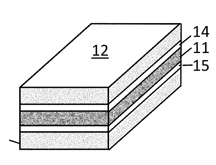
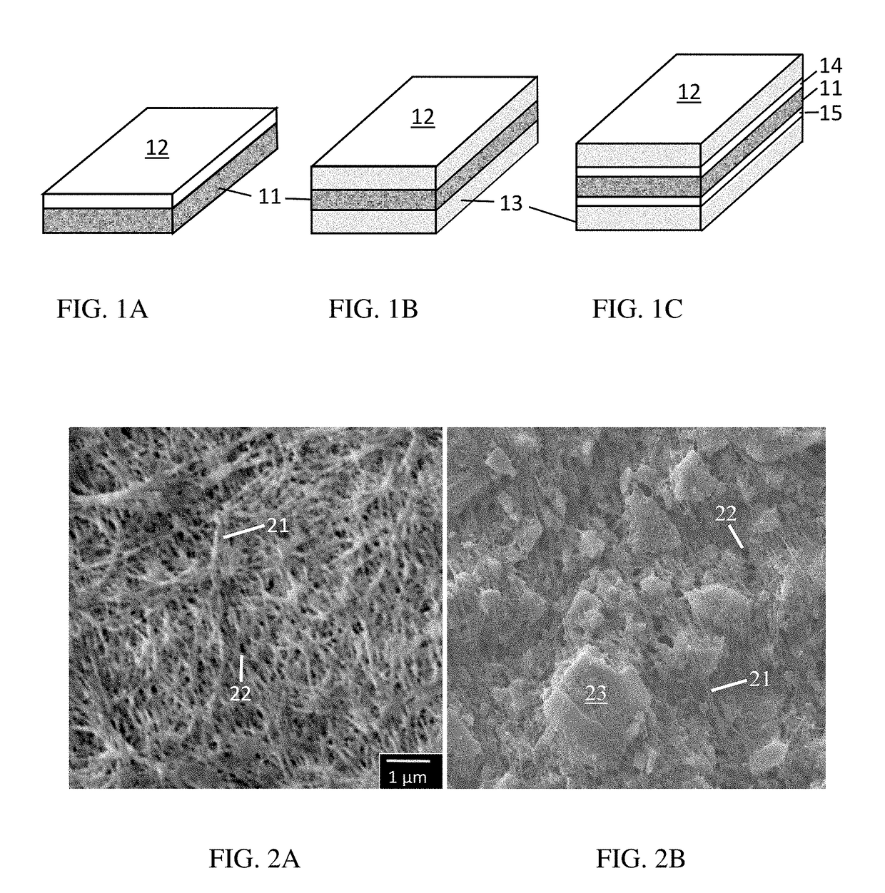
[0246]TABLE 4 shows the layer structure, composition and thickness of EXs 13-24. All the films had multiple layers with a total thickness of 7 to 20 μm. The EX 13 film was a dry 3-layer film of unfilled PO (U-PO), consisting of a PP / HDPE blend core coextruded with two β-PP skins. The EX 14 film was a 3-layer film of filled PO (F-PO) having two wet skins of 30 wt. % Al2O3. EXs 15 and 16 were a 2-layer film, consisting of the EX 8 film coated (C) or laminated (L) on one side. The wet coating contained 50 wt. % solids dispersed finely in water, comprising p-m-HDPE and Al2O3 both having an average particle size of 0.5 and 0.8 μm, respectively. The coating was applied with a gravure coater, and dried at 100° C. in a hot air oven. EX 17 was a 3-layer laminate, EXs 18 to 23 a coextruded 3-layer film, and EX 24 a 5-layer film having two maleated tie layers respectively to bond adjacent core-skin layers together. The porogens included metal oxides, zeolites, nanomaterials, immiscible polymer...


PUM

PropertyMeasurementUnit
porosityaaaaaaaaaa
Tgaaaaaaaaaa
particle sizeaaaaaaaaaa

Abstract

Provided is an oriented multilayer porous film comprising at least one layer comprising: a heat, solvent, and degradation resistant matrix polymer; a plurality of interconnecting pores; and a porosity less than 90%. The film is made by a dry and / or wet method, with its multilayer structure constructed by coextrusion, lamination, and coating. The film of this disclosure finds a wide range of applications as a permselective medium for use in energy harvesting and storage, filtration, separation and purification of gases and fluids, CO2 and volatile capture, electronics, devices, structural supports, packaging, labeling, printing, clothing, drug delivery systems, bioreactor, and the like. The film is preferably used as a separator of lithium-ion, lithium-sulfur, lithium-air, metal-air, and nonaqueous electrolyte batteries.

Description

FIELD OF THE INVENTION[0001]This invention pertains to an oriented multilayer porous film made from a broad range of heat, solvent and degradation resistant matrix polymers, compositions and structures, and to an article or device comprising the porous film of this disclosure.BACKGROUND OF THE INVENTION[0002]A porous polymeric film finds a wide range of applications as a permselective medium for use in energy harvesting and storage, filtration, separation and purification of gases and fluids, CO2 and volatile capture, electronics, devices, structural supports, packaging, labeling, printing, clothing, drug delivery systems, bioreactor, and the like. Such film can be manufactured by various different techniques. A porous film can be isotropic or anisotropic, depending on layer arrangement, conditions and processes of manufacture. The isotropic film generally is uniform throughout in composition and structure. The anisotropic film, on the other hand, is asymmetric that consists often o...

Claims


Application Information

Patent Timeline
Patent Type & Authority Applications(United States)
IPC IPC(8): B32B5/18C08J5/18C08J9/26H01M2/16H01G11/52H01M8/0245B32B27/08B32B27/20H01G9/02C08J9/28H01M8/0239H01M50/414H01M50/417H01M50/449H01M50/489H01M50/491H01M50/494
CPCB32B5/18C08J9/28C08J5/18C08J9/26H01M2/1653H01M2/1686H01M8/0239H01M8/0245B32B27/08B32B27/20H01G9/02H01G11/52C08J2300/00C08J2400/00C08J2201/0464C08J2203/08C08J2201/044C08J2201/0442C08J2201/0444C08J2203/182C08J2201/0422C08J2201/03H01M8/1044H01M8/1053Y02E60/50Y02E60/10H01M50/449H01M50/417H01M50/414H01M50/491H01M50/489H01M50/494Y02E60/13
Inventor SONG, KWANGJINSONG, JENNIFER M.SONG, JANE M.
Owner LISO PLASTICS L L C
Learn More