Electrochemical cell comprising channel-type flowable electrode units

a flowelectrode unit, channel-type technology, applied in electrochemical methods, electrochemical generators, chemistry apparatuses and processes, etc., can solve the problems of reducing the efficiency of extension capacity, reducing the efficiency of charge-discharge, and high equipment costs, so as to reduce manufacturing costs and installation space

Active Publication Date: 2018-05-03
KOREA INST OF ENERGY RES
View PDF4 Cites 4 Cited by
  • Summary
  • Abstract
  • Description
  • Claims
  • Application Information

AI Technical Summary

Benefits of technology

[0118]The channel-type flow-electrode structure according to the present invention including at least two channel-type flow-electrode units, can significantly reduce manufacturing costs and installation space by reducing the number of module parts while extending the electrode capacity to be suitable for large-scale plants for electricity generation, energy storage, desalination, etc. In addition, the channel-type flow-electrode structure can not only be applied to a capacitive flow-electrode device and / or a redox flow-electrode device, but also to all of the devices for electricity generation, energy storage, and desalination while moving ions or protons.

Problems solved by technology

For a power storage and water treatment system using the identical principles as described above, the most significant problem is the high cost of equipment as well as reduction of efficiency in the extension of capacity.
In other words, due to an increase in the surface area of electrodes for upscaling, and irregularities in the electrical field distribution of the electrode, limited amounts of active materials in thin film electrodes coated on current collectors, a decrease in the contact area between the active material and electrolyte by binders during coating, decrease in charge-discharge efficiency, and so forth, the number of unit cells must be stacked, thereby causing high equipment costs, and specifically, a capacitive deionization (CDI) process encounters the problem of increasing operational costs due to the loss of water (electrolyte) pressure in the stack flow.
However, in existing technologies, constitutional unit elements including positive and negative electrode collectors are infinitely stacked.
As a result, the stacking of the unit cells not only cause a greatly increased volume, but also has a problem in that the number of components increases due to a variety of flow channels, thereby increasing the costs of manufacturing an apparatus.

Method used


Image

  • Electrochemical cell comprising channel-type flowable electrode units
  • Electrochemical cell comprising channel-type flowable electrode units
  • Electrochemical cell comprising channel-type flowable electrode units

Examples


example 1

nnel-Type Flow-Electrode Structures

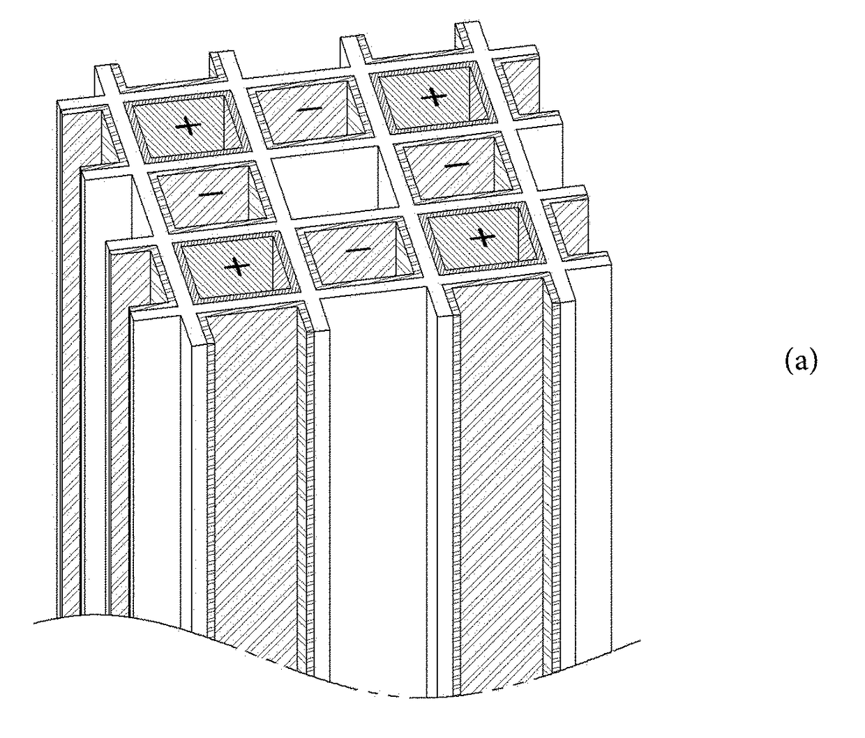
[0138]A channel-type electrode structure having three channels was manufactured as shown in FIG. 8.

[0139]Specifically, three-square-column-type channel scaffold was molded to prepare a liquid-permeable microporous honeycomb structure. The first square column channel was coated with a positive ion-exchangeable membrane, and the third square column channel was coated with a negative ion-exchangeable membrane. Thus, the positive ion-exchangeable membrane and the negative-exchangeable membrane respectively were formed on an inner wall surface of the channels. Additionally, graphene was coated on the inner wall surfaces of the first square column channel and third square column channel, which had been coated with the ion-exchangeable membranes, to form a porous current collector.

[0140]Therefore, a channel-type flow-electrode structure, in which the first square column channel provides a cathode flow channel along an inside of which a fluid containing a ...

example 2

nel-Type Flow-Electrode Structures

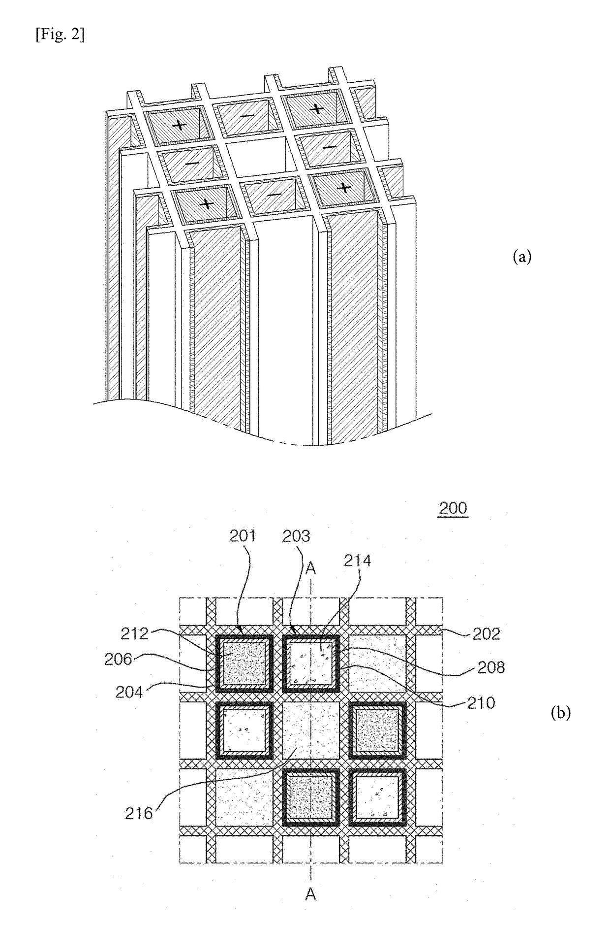
[0144]Nine channel-type flow-electrode structures as shown in FIG. 5a was manufactured in the same manner as in Example 1.

[0145]Additionally, the result of the experiment conducted in the same manner as in Example 1 is shown in Table 1 and FIG. 15.

[0146]The prepared cell was placed in a vessel containing saline solution (35 g / L), and a reaction was initiated. The amount of NaCl in the saline solution can be estimated by measuring the conductivity of the saline solution. In the case of the three-channel type cells, the conductivity of the initial saline solution (35 g / L) without a desalination reaction was 62 mS / cm, but the conductivity thereof after the desalination reaction was decreased to 50 mS / cm. As a result, the concentration of the saline solution was estimated to be 28 g / L, and the salt removal efficiency was 20%. When the cell was expanded to have nine channels, the conductivity was reduced to 8.15 mS / cm; the concentration of the saline sol...

example 3

nt of Desalination Parameters of 1×3 Cell and 3×3 Cell in Batch Mode

[0147]As described in a literature (i.e., A novel three-dimensional desalination system utilizing honeycomb-shaped lattice structures for flow-electrode capacitive deionization, Energy Environ. Sci., 2017, 10, 1746 to 1750), a desalination experiment was conducted in the batch mode of FIG. 17, and the literature above is included in the present invention.

[0148]The dimensions of lattice structures were 3 mm in width, 0.5 mm in wall thickness, and 120 mm in height. The cordierite was used to form porous channels with the size ranging from 10 μm to 30 μm, and an ion-exchangeable membrane was coated on its surface. On the top thereof, about 30 μm of a graphene layer was coated to serve as a conducting current collector. The prepared cell was immersed in the chamber containing saline solution (35 g / L), and then the desalination experiment was conducted in the batch mode. The salt removal efficiency was calculated by the ...


PUM

PropertyMeasurementUnit
conductivityaaaaaaaaaa
concentrationaaaaaaaaaa

Abstract

The present invention relates to an electrochemical cell having a channel-type flow-electrode unit.
The channel-type flow-electrode structure according to the present invention, which has at least two channel-type flow-electrode units, can significantly reduce manufacturing costs and installation space by reducing the number of parts while extending the electrode capacity to be suitable for large-scale plants for electricity generation, energy storage, desalination, etc. In addition, the channel-type flow-electrode structure can be applied not only to a capacitive flow-electrode device and/or a redox flow battery device, but also to all of the devices for electricity generation, energy storage, and desalination while moving ions or protons.

Description

TECHNICAL FIELD[0001]The present invention relates to an electrochemical cell comprising channel-type flow-electrode unit structures.BACKGROUND ART[0002]In recent years, many countries have devoted great efforts to developing clean energy alternatives in order to solve the problems of atmospheric environmental pollution and global warming. In particular, marine salinity gradient power generation recently has received much attention.[0003]At the same time, the development of large-capacity electric power storage technology capable of storing electric energy generated by various alternative energies has been raised as a key point in the foundation of the green industry of the future. Most such future technologies for power storage are based on the principles of ion absorption (charge) and desorption (discharge) such as Li-ion batteries or super capacitors, and therefore, countries over the world are proceeding with major research and development efforts to accomplish high-efficiency d...

Claims


Application Information

Patent Timeline
Patent Type & Authority Applications(United States)
IPC IPC(8): H01M8/0258H01M8/18C02F1/46C02F1/461
CPCH01M8/0258H01M8/188C02F1/4604C02F1/46109C02F2001/46171C02F1/4695H01M8/18Y02A20/124Y02E60/50
Inventor KIM, DONG-KOOKJEON, SUNG-ILCHOO, KO-YEONCHO, YOUNGHYUNYEO, JEONG-GUPARK, JONG-SOOYANG, SEUNGCHEOLCHOI, JI YEONPARK, HONG RANLEE, KI SOOKYOUN, YOUNG JIKLEE, JUNG HYUNKIM, HEE-YEON
Owner KOREA INST OF ENERGY RES
Why Eureka
Try Eureka