Micro evaporator, oscillator integrated micro evaporator structure and freqency correcton method thereof

Inactive Publication Date: 2018-12-06
SHANGHAI INST OF MICROSYSTEM & INFORMATION TECH CHINESE ACAD OF SCI
View PDF0 Cites 1 Cited by
  • Summary
  • Abstract
  • Description
  • Claims
  • Application Information

AI Technical Summary

Benefits of technology

[0033]The micro evaporator, the oscillator integrated micro evaporator structure and the frequency correction method thereof provided by the present invention have the following beneficial effects: the micro evaporation platform is connected with the anchor points with the metal electrodes formed on the surfaces through the supporting beams, and by adjusting and setting the size of the supporting beams, the supporting beams are enabled to have the features of small heat capacity and less heat dissipation; since the sizes of the micro evaporation platform and the supporting beam are small, the mic

Problems solved by technology

In modern communication systems, since frequency resources are limited and users are numerous, an extremely high requirement is raised to the accuracy of oscillator frequency.
However, quartz crystal oscillator is difficult to integrate quartz oscillators, it is difficult to manufacture high-frequency oscillators due to limitations of machining means, and the anti-vibration performance of quartz crystal oscillator is poor, thus it is difficult to satisfy the requirement of mobile intelligent devices.
One major problem which must be solved by oscillators is that the discreteness of MEMS oscillator frequency is caused to be great since the discreten

Method used


Image

  • Micro evaporator, oscillator integrated micro evaporator structure and freqency correcton method thereof
  • Micro evaporator, oscillator integrated micro evaporator structure and freqency correcton method thereof
  • Micro evaporator, oscillator integrated micro evaporator structure and freqency correcton method thereof

Examples


embodiment 1

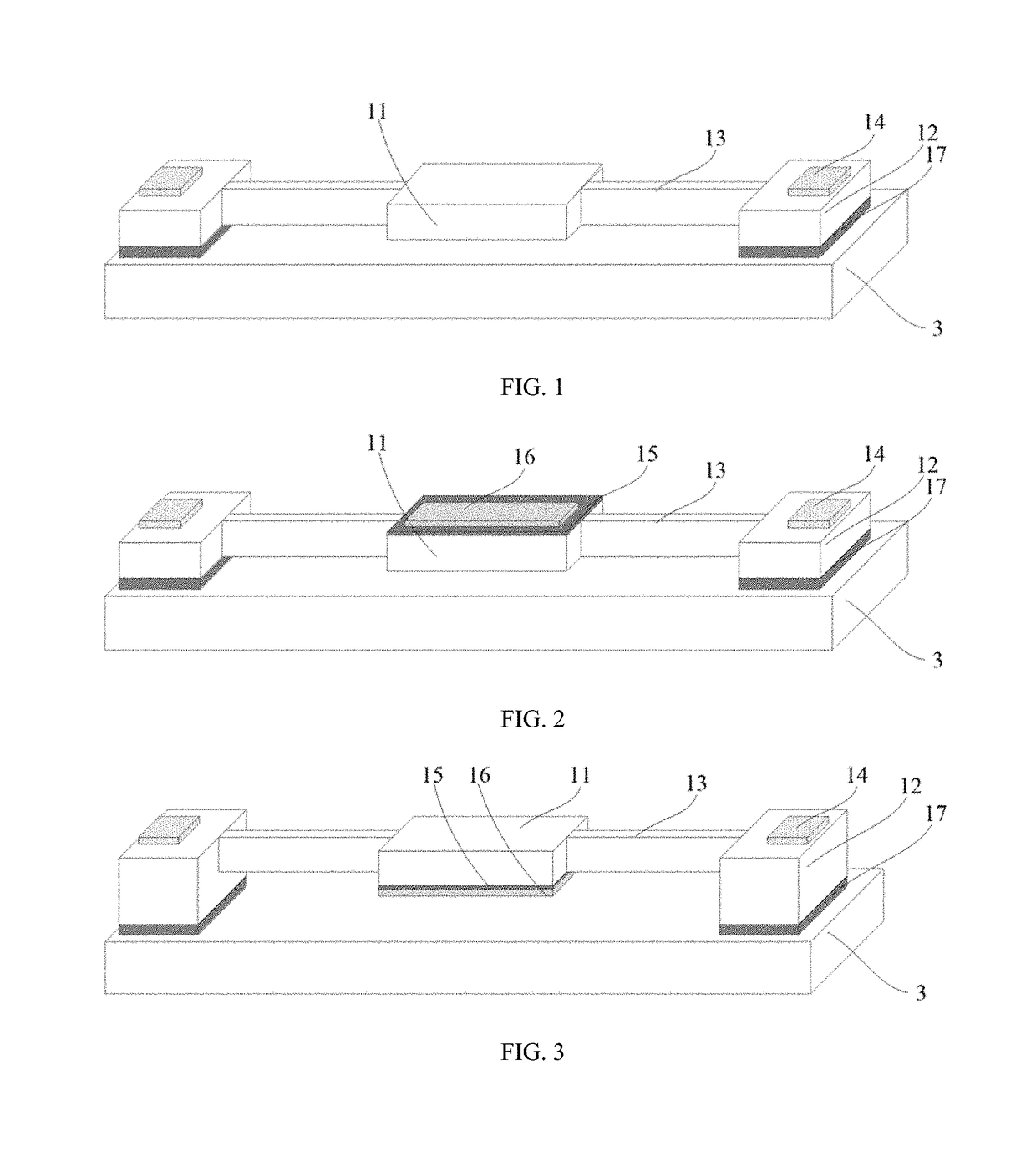
[0049]Please referring to FIG. 1, the present invention provides a micro evaporator, and the micro evaporator comprises a micro evaporation platform 11, anchor points, supporting beams and metal electrodes; in order to facilitate distinguishing from subsequent other structures, the anchor points, the supporting beams and the metal electrodes here are respectively defined as first anchor points 12, first supporting beams 13 and first metal electrodes 14;

[0050]one surface of the micro evaporation platform 11 is an evaporation surface; the first anchor points 12 are located on two sides of the micro evaporation platform 11 and have a certain distance to the micro evaporation platform 11; the first supporting beams 13 are located between the micro evaporation platform 11 and the first anchor points 12, one end of each first supporting beam 13 is connected with the micro evaporation platform 11 and the other end is connected with the first anchor point 12; the size (i.e., length, width a...

embodiment 2

[0057]Please referring to FIG. 2 to FIG. 3, the present invention further provides a micro evaporator, the structure of the micro evaporator is approximately the same as the structure of the micro evaporator in embodiment 1, and the micro evaporator in this embodiment differs from the micro evaporator in embodiment 1 in that:

[0058]the micro evaporator further comprises an evaporation material 16 and the evaporation material 16 is located on the evaporation surface of the micro evaporation platform 11.

[0059]As an example, when saturated vapor pressure is greater than 10−6 Torr, temperature of the evaporation material 16 is lower than the melting point of the micro evaporation platform 11. The evaporation material 16 may be selected to be metal, semiconductor or insulating materials, e.g., aluminum, germanium, gold or semiconductor materials such as silicon or germanium. The micro evaporator and the oscillator are integrally used to correct the resonance frequency of the oscillator, t...

embodiment 3

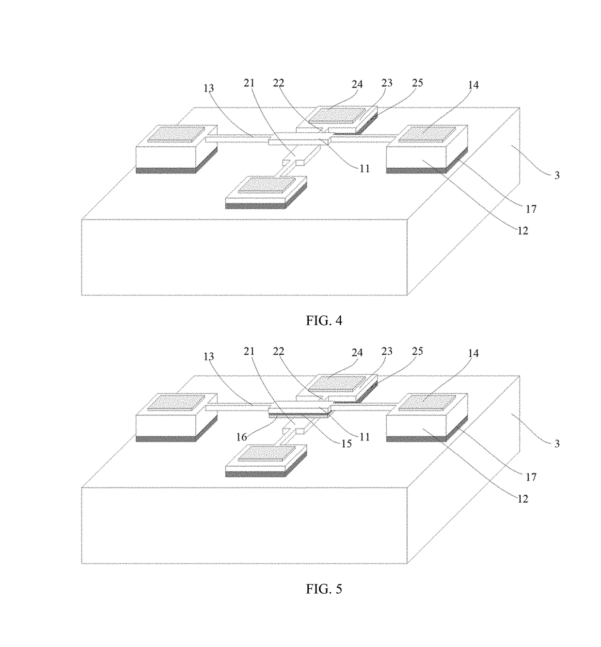
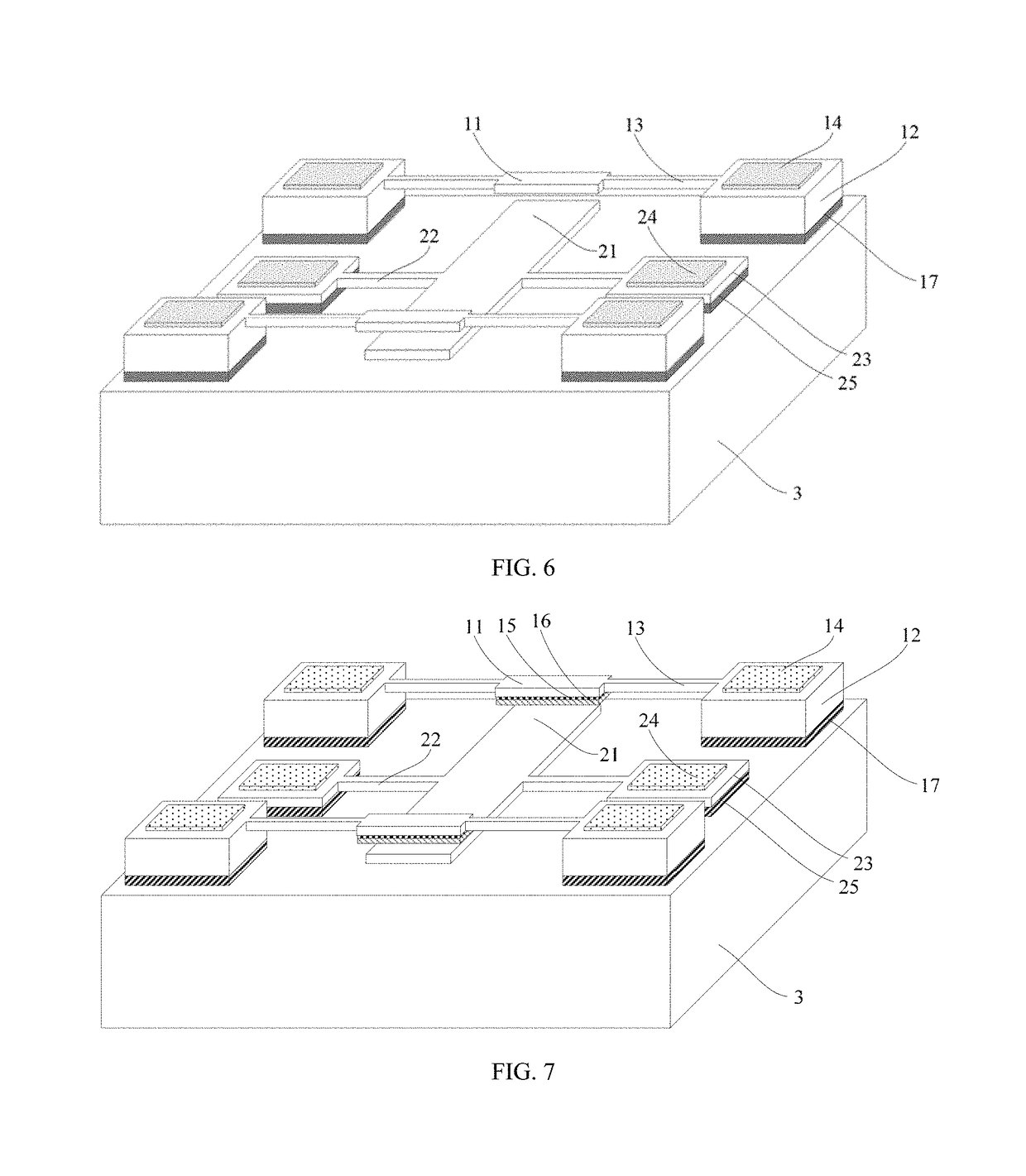
[0064]Please referring to FIG. 4, the present invention provides an oscillator integrated micro evaporator structure, and the oscillator integrated micro evaporator structure comprises the micro evaporator in embodiment 1 and an oscillator; and

[0065]the micro evaporator and the oscillator are jointly sealed in a same vacuum chamber, the micro evaporator and the oscillator are arranged in upper and lower correspondence, and the evaporation surface of the micro evaporation platform 11 in the micro evaporator faces to the oscillator.

[0066]As an example, the oscillator may be a quartz oscillator, or a silicon-based MEMS oscillator, or any one other oscillator, and the type and structure of the oscillator are not limited herein, i.e., the oscillator may be any one of existing oscillators.

[0067]In this embodiment, by taking a bending-mode oscillator as an example, the oscillator comprises a resonance unit 21, second supporting beams 22, second anchor points 23, and second metal electrodes...


PUM

PropertyMeasurementUnit
Vapor pressureaaaaaaaaaa
Temperatureaaaaaaaaaa
Thicknessaaaaaaaaaa

Abstract

The present invention provides a micro evaporator, an oscillator integrated micro evaporator structure and a frequency correction method thereof. The micro evaporator comprises a micro evaporation platform, anchor points, supporting beams and metal electrodes, wherein one surface of the micro evaporation platform is an evaporation surface; the anchor points are located on two sides of the micro evaporation platform and have a certain distance to the micro evaporation platform; the supporting beams are located between the micro evaporation platform and the anchor points, one end of each supporting beam is connected with the micro evaporation platform and the other end is connected with the anchor point; the size of each supporting beam satisfies the following relation: T=P(L/2kbh)+Ta; and the metal electrodes are located on first surfaces of the anchor points.

Description

BACKGROUND OF THE PRESENT INVENTIONField of Invention[0001]The present invention belongs to the field of sensing technologies, and in particular relates to a micro evaporator, an oscillator integrated micro evaporator structure and a frequency correction method thereof.Description of Related Arts[0002]An oscillator is a basic element for providing clock frequency in a digital electronic system, and is used in almost all electronic systems. In modern communication systems, since frequency resources are limited and users are numerous, an extremely high requirement is raised to the accuracy of oscillator frequency. GSM mobile phones require the frequency accuracy of oscillators to be within ±2.5 ppm, while mobile base stations require the stability of oscillators to be within ±0.05 ppm.[0003]For a long time, quartz crystal oscillators are always main elements for providing clock frequency signals in electronic systems fonts stable performance and good temperature characteristic. Howeve...

Claims


Application Information

Patent Timeline
IPC IPC(8): C23C14/24H03H9/24H03B1/02H01L21/02
CPCC23C14/24H03H9/24H03B1/02H01L21/02491H01L21/02488H01L21/0242H01L21/02631B81B3/0078B81B2201/0271B81B2203/0109H01L21/02532H03H3/0077H03H9/02401H03H9/1057
Inventor YANG, HENGYOU, WEILONGZHANG, LEIWANG, XIAOFEILI, XINXIN
Owner SHANGHAI INST OF MICROSYSTEM & INFORMATION TECH CHINESE ACAD OF SCI
Why Eureka
Try Eureka