
Method and Device for Increasing Laser-Induced Shock Wave Pressure

a laser-induced shock wave and pressure technology, applied in the field of laser shock processing, can solve the problems of high-power lasers that cannot be practically applied in the laser shock strengthening field, the restraint device of these methods is complex, and the cost is significan

Active Publication Date: 2019-01-10
JIANGSU UNIV
View PDF2 Cites 4 Cited by
  • Summary
  • Abstract
  • Description
  • Claims
  • Application Information

AI Technical Summary

Benefits of technology

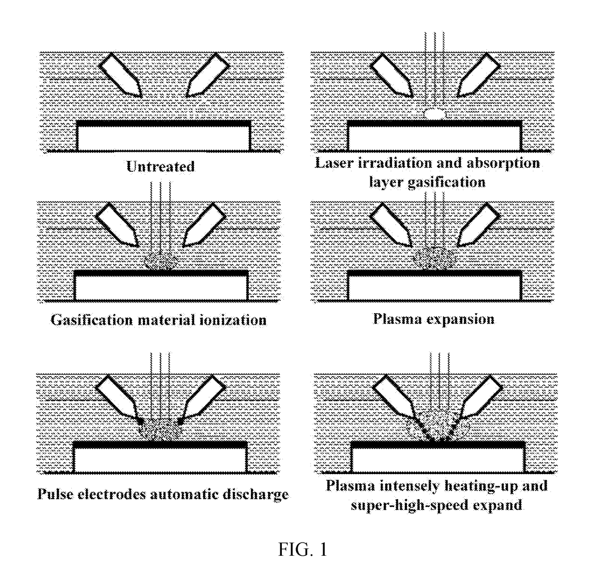
The present invention provides a method and device for improving laser-induced shock wave pressure. This method utilizes high-temperature plasma generated by a laser-induced aluminum foil and a photoelectric composite energy field to increase the pressure by several tens of times under the same laser energy. The method has the advantage of being simple, easy to implement, and low-cost and high-automation device. The device has a high surface to be processed, such as high-strength materials, and can be easily impacted by the high-temperature plasma to strengthen the surface and improve its performance.

Problems solved by technology

However, at present, due to the limitations of factors such as light frequency, control accuracy, operation cost and volume size, the high power lasers cannot be practically applied in laser shock strengthening field.
Therefore, it is a key technical problem in the field of laser shock strengthening to enhance the pressure of laser induced shock wave pressure on the basis of the existing laser energy level.
Although these methods make up for some shortage of conventional water screen confinement layer to a certain extent and improve the laser induced shock wave pressure, these methods do not change the generation process of shock wave.
Thus, it is impossible to realize the multiple increase of laser shock wave pressure.
And the restraint devices of these methods are complex and also cost significantly.
However, this method still cannot realize the multiple increase of laser shock wave pressure.
At the same time, it is difficult to achieve multi-point continuous shocking or multi-point overlapping shocking due to that the water film is difficult to keep clean and is easy to splash, and the replacement is complex.
But the following problems still exist: (1) When the shock waves propagate through the pipe, the pressure decays rapidly, which limit the increase of shock wave pressure generated during the continuous explosion of plasma and makes it difficult to grow exponentially; (2) Shock waves generated by multiple continuous detonation need to be superimposed in multiple times, which requires a very high demand on the control of the explosion time, which further affects the superimposition of shock waves and then reduces the shock wave pressure after multiple error accumulation; (3) The continuous explosion takes a long time, which reduces the processing efficiency.
This method has a certain effect on improving the shock wave pressure, but compared to the present application, there are still some deficiencies as follows: (1) Due to the concentration and the charge number of charged particles in the plasma are not uniform, and the motion state changes over time, it is difficult to adjust the size and direction of the magnetic field and the electric field to match them, thus it is difficult to increase the pressure of the shock wave manyfold; (2) In the plasma, since the mass of the charged particles such as electrons are very small and the velocity is very high, it is hard to restrain the charged particles through the magnetic field and the electric field.
The reduction of the constraint effect makes it difficult to achieve a multiply increase of the shock wave pressure; (3) The high difficulty in this technology will inevitably lead to complex devices, complicated operation and high cost, so it is difficult to achieve engineering applications.

Method used

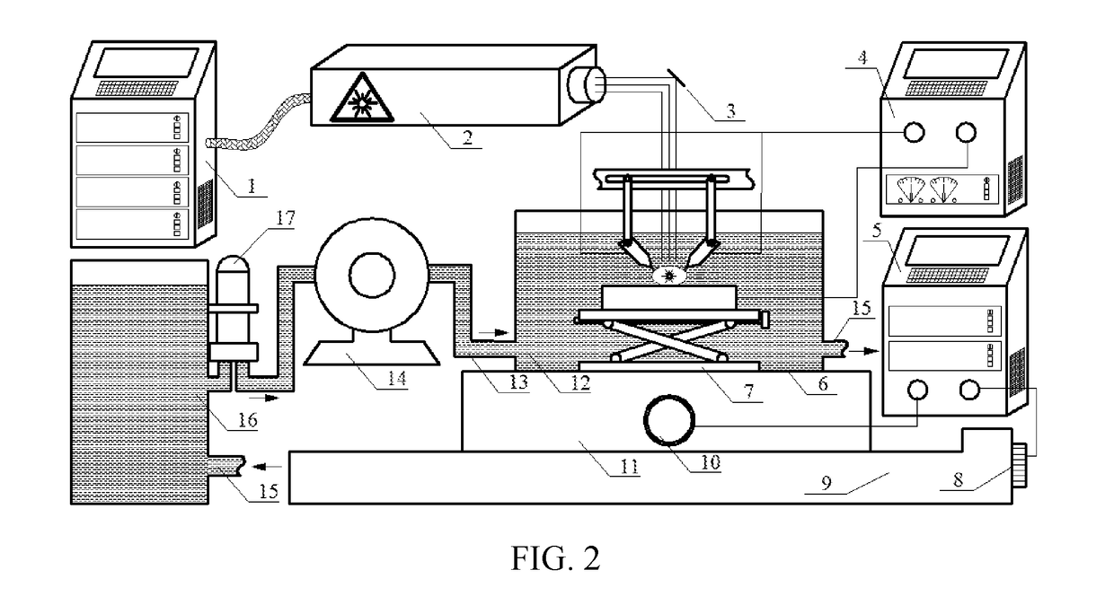

Image

  • Method and Device for Increasing Laser-Induced Shock Wave Pressure
  • Method and Device for Increasing Laser-Induced Shock Wave Pressure
  • Method and Device for Increasing Laser-Induced Shock Wave Pressure

Examples


example 1

[0028]Taking TC4 aerospace titanium alloy as an example, a method that greatly increases the laser induced shock wave pressure by utilizing the auto-induced composite energy field is employed to strengthen this material. Wherein, the laser is a French Thales nanosecond laser, and the laser pulse width is 20 ns. An aluminum foil with a thickness of 120 μm is selected as the absorbing layer. Deionized water is selected as the discharge medium. Symmetrical electrodes are electroforming Cu. The number of electrodes is 2 and the voltage of the high voltage power supply is set to 480 V. The methods and steps are as follows:

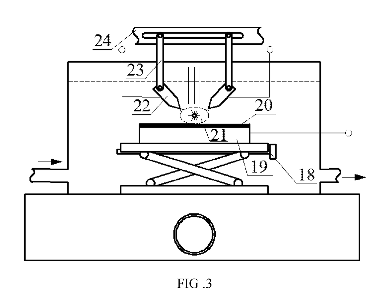
[0029]A. Adjusting the electrode spacing L2 between the symmetrical electrodes 22 and the distance L1 between the discharge end of electrode and the spot center on the surface of aluminum foil 20 to 0.5˜0.8 R; adjusting the output voltage of the high voltage power supply 4 to the critical voltage to ensure that the symmetrical electrodes 22 can be automatically triggere...

example 2

[0037]A device for improving the laser induced shock wave pressure includes a laser shock system, a pulse discharge system and a motion platform system. Wherein, the laser shock system comprises a laser 2, a control system 1 and a 45° total reflection mirror 3. The laser 2 is connected with the control system 1 through the data lines. In the pulse discharge system, the symmetrical electrodes are connected with the horizontal sliding rail 24 by the hanging bracket 23 to ensure the electrode spacing L2 is adjustable. The symmetrical electrodes 22 are connected to the high-voltage power supply 4 through high-power wire. The discharge medium 12 is pumped into the discharge tank via the entrance 13 of the discharge tank by the fluid pump 14. A filter is arranged between the fluid pump 14 and storage tank 16. The discharge medium 12 in the discharge tank flows back into the storage tank 16 through outlet port 15 of the discharge tank. The motion platform system comprises an X direction ta...


PUM

PropertyMeasurementUnit
thicknessaaaaaaaaaa
voltageaaaaaaaaaa
pressureaaaaaaaaaa

Abstract

A method and a device for increasing a laser induced shock wave pressure. According to the method, plasmas (21) are generated by impinging an aluminium foil (20) using lasers; a high-voltage pulse electrode (22) discharges to the plasmas (21) to induce and form a photoelectric combined energy field and then high-temperature plasmas (21) having the characteristics of an ultra-high density and an ultra-high speed expansion are induced and generated; a surface to be processed is impacted by the high-temperature plasmas (21) in a restrained state; the laser induced shock wave pressure is increased substantially; the surface of a high-strength material is reinforced, and the strength, hardness, abrasion resistance and anti-fatigue performances of the high-strength material are improved. The device comprises a laser, the electrode (22), a high-voltage power supply (4), a discharging medium (12), a moving platform, etc.

Description

TECHNICAL FIELD[0001]The present invention relates to the technical field of laser shock processing, particularly to laser shocking strengthening technology, in particular to method and device for increasing laser induced shock wave pressure by utilizing the automatically induced composite energy field.TECHNICAL BACKGROUND[0002]Laser shock strengthening is a new surface deformation strengthening technology. It utilizes stress strengthening and microstructural strengthening induced by high-energy and short pulse laser to realize the surface modification of materials. Compared with the traditional surface strengthening technology, it has distinct characteristics of high voltage (GPa), fast process (ns), high strain rate (107 s−1) and so on, and has significant technical advantages in the controllable strengthening treatment of stress concentration areas of key thin-walled structures in aerospace.[0003]However, process parameters such as laser energy, laser spot diameter and so on, nee...

Claims


Application Information

Patent Timeline
Patent Type & Authority Applications(United States)
IPC IPC(8): C21D10/00B23K26/356
CPCB23K26/356C21D10/005B23K26/122B23K26/348C21D10/00
Inventor ZHOU, JIANZHONGMENG, XIANKAIHUANG, SHUSHENG, JIESU, CHUNZHOU, HONGDAYANG, XIANGWEICHEN, HANSONG
Owner JIANGSU UNIV
Learn More