
Gels and nanocomposites containing anfs

a nano-composite and gel technology, applied in the field of gels and nano-composites containing anfs, can solve the problems of complex incorporation of matrix components into produced 3dns that complement the base high-strength nanomaterials, difficult to produce 3dpns, and inability to fully penetrate polymers into nanopores, etc., and achieve the effect of continuous production

Active Publication Date: 2019-03-21
RGT UNIV OF MICHIGAN
View PDF0 Cites 26 Cited by
  • Summary
  • Abstract
  • Description
  • Claims
  • Application Information

AI Technical Summary

Benefits of technology

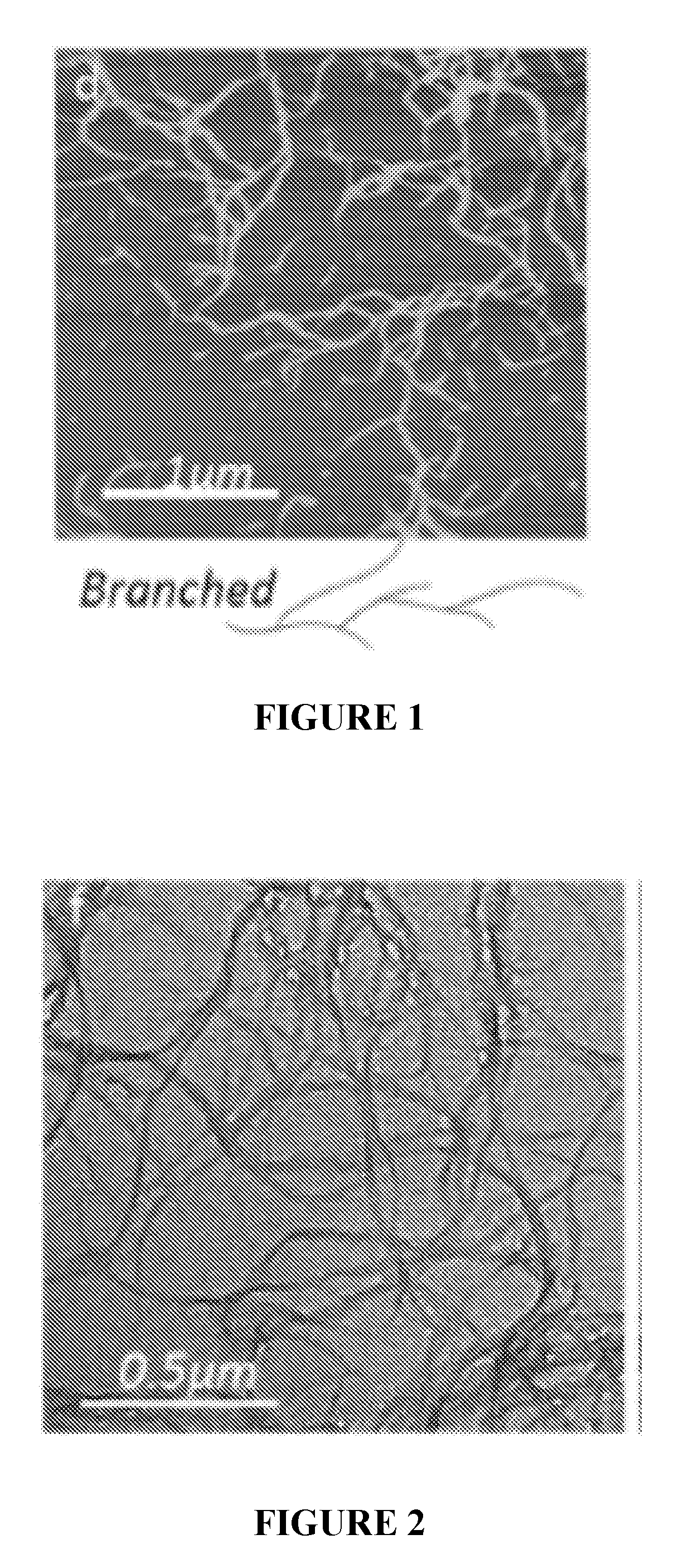
The patent describes a method for making high-performance nanocomposite materials using a layer-by-layer (LBL) assembly process. This technique can produce materials with uniformly distributed nanomaterials and high volume fractions. However, LBL deposition can require slow and multilayer build-up, which can be time-consuming. To address this problem, the patent proposes using suspensions of branched nanofibers, which can accelerate the deposition process and produce thicker films of high-performance composites. The branched nanofibers can form robust gels, which can be used in LBL assembly and can lead to consistent and controlled fabrication of nanocomposites with nanoscale level control.

Problems solved by technology

However, 3DPNs are difficult to produce due to their collapse under capillary pressure and poor connectivity of the nanomaterials.
Their percolations are generally achieved through the direct contact with each other on the confined cross-area by limited molecule forces, which could be easily disrupted by mechanical disturbance, such as shearing or stretching.
(1, 2) However, the long times associating with diffusion of the polymers, incomplete penetration of polymers into nanopores.
Furthermore, incorporation of the matrix components into produced 3DNs that complement the base high strength nanomaterials, is complicated by the immiscibility of solvents, incompatibility of properties, 3DPN collapse, phase separation, and other problems.
However, LBL deposition often requires depositing one nanometer scale layer at a time.
(3, 4) However, this method brings about limitations exemplified by need for the two components to be dispersed in the same solvent, otherwise, bulk agglomeration and phase separation occur and preparation of VAF films become impossible.
If the components are strongly attracted to each other (which is desirable for mechanical performance of the resulting composite film) microporous filter membrane used in filtration of the composites becomes plugged and the separation of the composite phase from the fluid phase becomes impossible.

Method used


Image

  • Gels and nanocomposites containing anfs
  • Gels and nanocomposites containing anfs
  • Gels and nanocomposites containing anfs

Examples


example 1

Composites—or ANF / EPX Composites

[0174]Branched ANF dispersion can be prepared by dispersing aramid microfiber (or commonly known as Kevlar fibers) in DMSO mixed with water and a base in specified concentrations. A subsequent solvent exchange with water leads to the formation of ANF hydrogel in a process step called phase transforming. In order to make a 3DPN in the form of ANF hydrogel coating, a thin liquid layer of branched ANF dispersion is spin-coated on a glass substrate and subjected to solvent exchange. The resulting thin ANF hydrogel can be carefully peeled off from the substrate (FIG. 23) and dried by supercritical CO2 to examine the structure (FIG. 24). In a non-limiting example, the obtained 3DPN is 57 μm thick slab with a wide range of pores defined by interconnected ANFs (FIG. 25).

[0175]To make the ANF / EPX composites, the branched ANF hydrogel layer is left on the substrate to allow the diffusion of EPX. The hydrogel is adhesive enough to the substrate to allow EPX to d...

example 2

om ANF Hydrogels

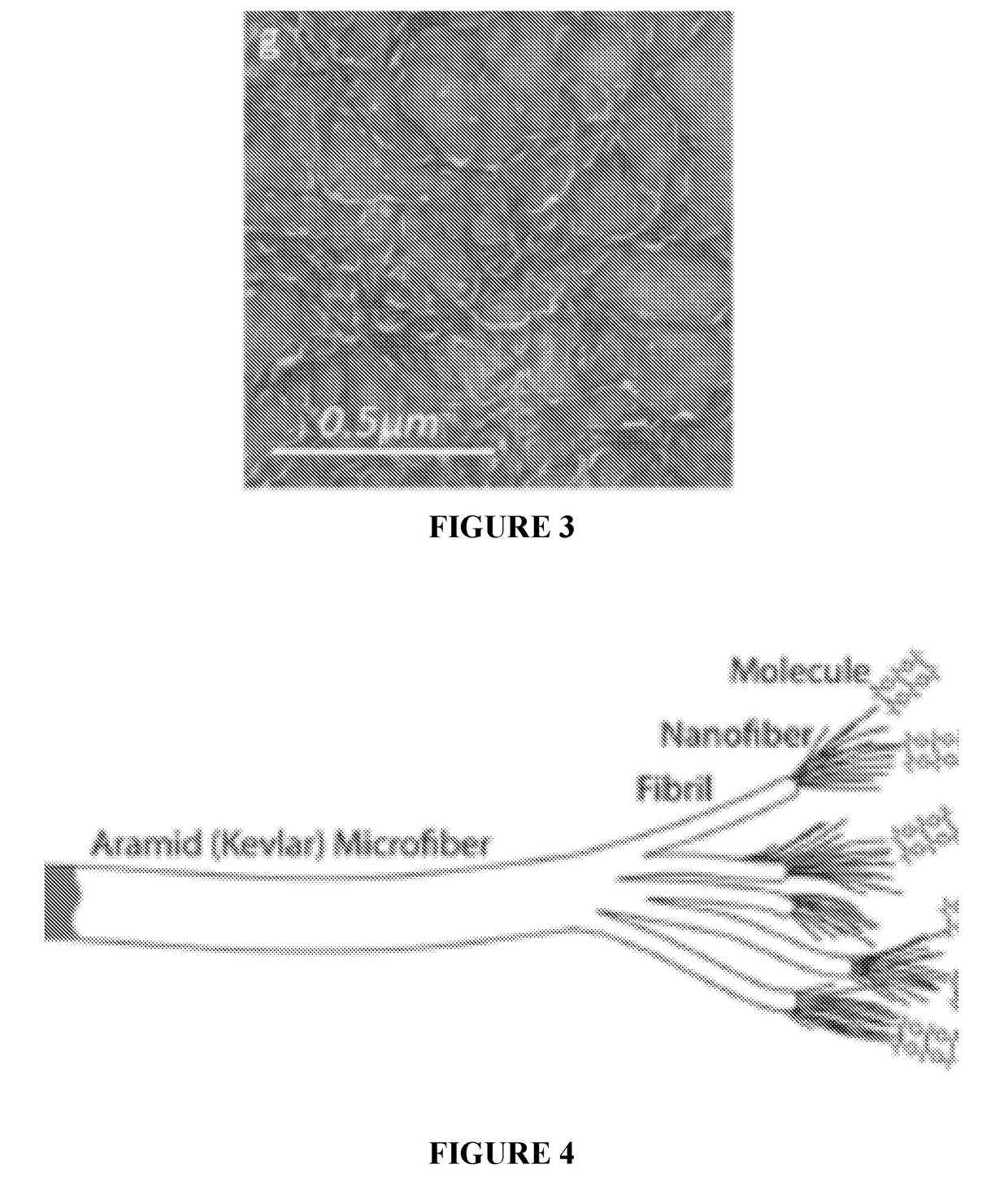
[0190]High aspect ratio plus the branched morphology makes ANF a unique nanoscale material for forming the 3DPNs. The latter can be formed in the form of hydrogels using a solvent exchange process described above (FIGS. 10, 12 and 49). In a typical procedure, a layer of water is gently sited on top of the DMSO-based dispersion phase containing 1 wt % ANF. With the slow diffusion of water, the deprotonated aramid chains are gradually reverted to their initial chemical structures by abstracting protons from water, accompanied by a color change from dark red to light yellow. The attained hydrogel is highly robust, and can sustain structural integrity even after cutting and shearing with a razor blade (FIG. 11). To further reveal the internal structure of ANF in the hydrogel, it is converted into an aerogel through the supercritical CO2 extraction (FIG. 13-15). As expected, the aerogel contains a network of highly branched ANF nanofibers entangled with each other. The AN...

example 3

on of ANF Continuous Gel Fiber

[0198]0.1% ANF dispersion was extruded from a 28 G stainless steel needle at a rate of 3 ml / h into a flow of DI water with a rate of 12 ml / h. The continuous gel fiber was immediately formed at the tip of the needle and was guided into a 0.58 mm (ID) glass capillary tube, and then collected in a DI water reservoir. The flow rate control was achieved by syringe pumps, and soft silicone tubing was used to make the connection.


PUM

PropertyMeasurementUnit
Fractionaaaaaaaaaa
Fractionaaaaaaaaaa
Percent by massaaaaaaaaaa

Abstract

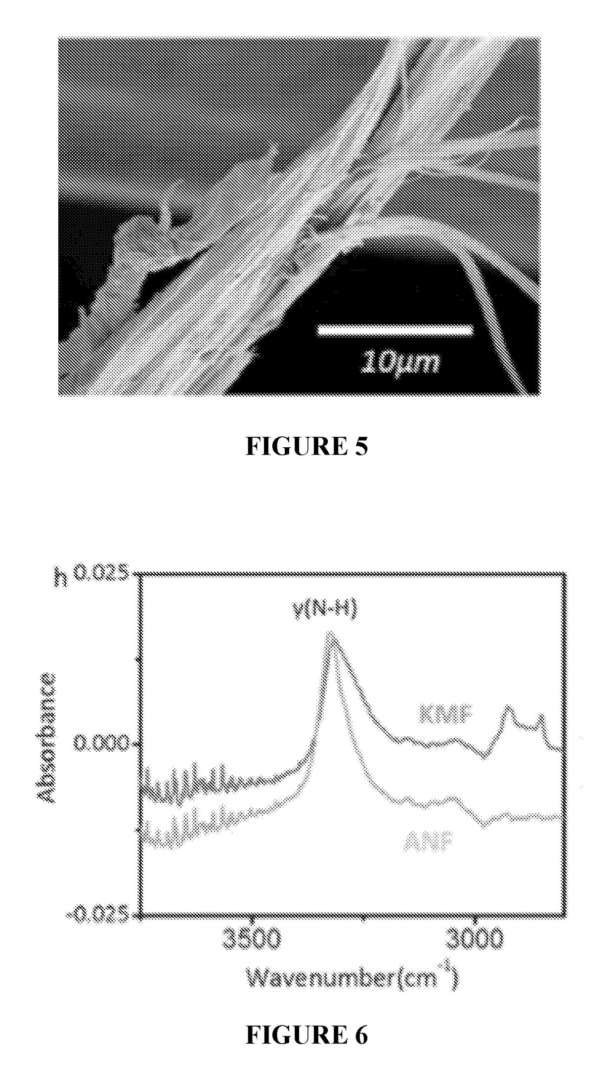
Branched aramid nanofibers (ANFs) can be made by controlled chemical splitting of micro and macroscale aramid fiber by adjusting the reaction media containing aprotic component, protic component and a base. Branched ANFs have uniform size distribution of diameters in the nanoscale regime (below 200 nm) and high yield exceeding 95% of the nanofibers with this diameter. The method affords preparation of branched ANFs with 3-20 branches per one nanofiber and high aspect ratio. Branched ANFs form hydrogel or aerogels with highly porous 3D percolating networks (3DPNs) frameworks that are made into different shapes. Polymers and nanomaterials are impregnated into the 3DPNs through several methods. Gelation of branched ANFs facilitates layer-by-layer deposition in a process described as gelation assisted layer-by-layer deposition (gaLBL). A method of manufacturing battery components including ion conducting membranes, separators, anodes, and cathodes is described. The method of manufacturing of materials with high mechanical performance based on branched ANFs and 3DPNs from them is disclosed.

Description

CROSS-REFERENCE TO RELATED APPLICATIONS[0001]This application claims the benefit of U.S. Provisional Application No. 62 / 272,877, filed on Dec. 30, 2015. The entire disclosure of the above application is incorporated herein by reference.GOVERNMENT SUPPORT[0002]This invention was made with government support under grants CBET1036672 and CBET0932823 awarded by the U.S. National Science Foundation. The government has certain rights in the invention.INTRODUCTION[0003]One-dimensional (1D) nanoscale components can form light-weight highly interconnected three dimensional percolated networks (3DPNs) with considerably improved physical properties, such as high mechanical and electrical performance in comparison to their non-percolating analogs. The designation of “percolating” means that there is a connected path through the network that extends in all three directions. Formation of 3DPNs can greatly increase the mechanical, electrical, optical, and biological properties of the material. How...

Claims


Application Information

Patent Timeline
IPC IPC(8): C08J5/04C08J3/075C08K9/00C08L77/06C08L63/00B29B15/08B29B13/06H01M4/04H01M10/0565H01M10/058
CPCC08J5/046C08J3/075C08K9/00C08L77/06C08L63/00B29B15/08B29B13/06B82Y30/00B82Y40/00C08L2203/20C08L2205/16C08L77/10C08J5/005C08J5/18C08J2363/00C08J2477/10C08J2377/10Y02P70/50B82B3/0009C08J3/20B82Y25/00C08J2205/026
Inventor KOTOV, NICHOLAS A.ZHU, JIANTUNG, SIU ON
Owner RGT UNIV OF MICHIGAN
Learn More