Durable white inorganic finish for aluminium articles

a technology of inorganic finish and aluminium, which is applied in the direction of electrolytic coating, surface reaction electrolytic coating, coating, etc., can solve the problems of low strength of alloys, limiting the application of alloys, and the stability of electrolyte systems is not particularly stable, so as to achieve high-quality external applications

Active Publication Date: 2019-06-13
KERONITE INT LTD
View PDF0 Cites 0 Cited by
  • Summary
  • Abstract
  • Description
  • Claims
  • Application Information

AI Technical Summary

Benefits of technology

[0038]Embodiments of the present disclosure provide coatings having a white inorganic finish that are UV stable, and are therefore highly suitable for external applications including architectural use and spacecraft / satellites.

Problems solved by technology

This is one of the simpler electrolyte systems and is not particularly stable.
However, such crystallization is a purification process that tends to drive impurities into grain boundaries in the form of other oxides and compounds.
Thus, at higher thickness, typically >10 μm, these finishes have a tendency to discolour.
Such alloys typically have low strength that limits their application.
The disadvantage of this method is that the resulting coatings are not especially white with L* values in the range 70-79%.
Furthermore they tend to have a coarse microstructure and low crystallinity.
Such coatings commonly suffer from similar problems.

Method used


Image

  • Durable white inorganic finish for aluminium articles

Examples


example 1

[0042]An article of aluminium 6082 alloy was placed in an electrolyte bath containing a solution of 2 wt % ammonium phosphate, 1 wt % acetic acid, 1 wt % potassium hydroxide and 1 wt % sodium tetrafluoroborate. Anodic voltage pulses were applied with a voltage of 480V, the discharge power was maintained below 15 W, and the process was continued until the coating reached 40 μm thickness. At the end of the process, the anodic breakdown voltage of the coating in the bath was measured to be 290V.

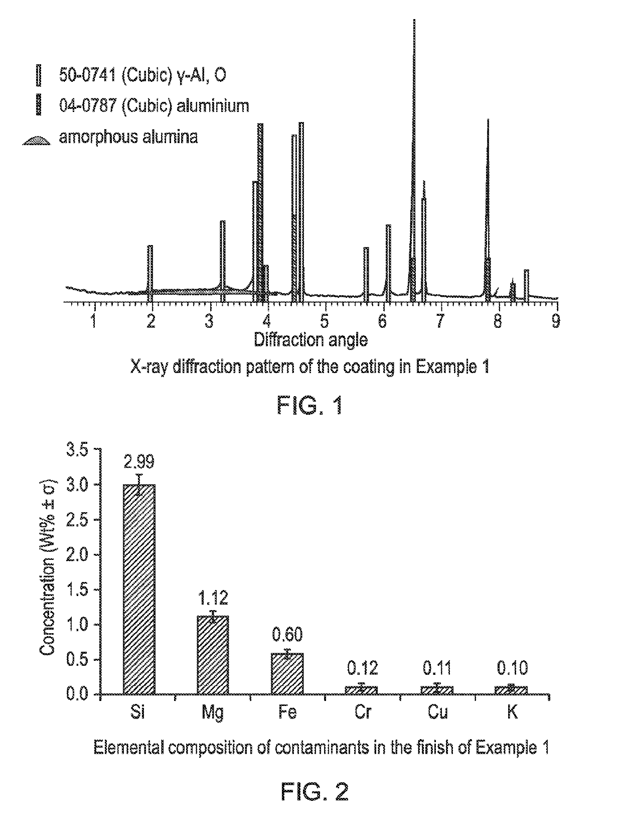
[0043]X-ray diffraction was performed in Bragg-Brentano geometry, from 5-90° 2q, with 2 second, 0.02° steps in a 40 kV, 40 mA Phillips PW1830 Diffractometer. The resulting spectrum (FIG. 1) shows that the coating consists primarily of gamma phase alumina with a small amount of amorphous material. The coating had a white appearance and luminosity was measured on a Konica Minolta spectrometer using the CIE L*a*b* colour space to be 82.6%.

[0044]The elemental composition of the finish was measured u...

example 2

[0045]An article of 2219 alloy, containing nominally 6 wt % Cu, was placed in a bath containing a solution of 3 wt % trisodium phosphate, 1 wt % ammonium hydroxide, 1 wt % citric acid and 0.5 wt % sodium fluoride and anodic pulses of 350V were applied, alternated with cathodic pulses of 100V. Discharge power was maintained below 15 W by adjusting the duration of the pulses. The process was continued until the coating thickness reached 15 μm. At the end of the process, the anodic breakdown strength of the coating in the electrolyte was measured to be 195V. The resulting coating was X-rayed and found to comprise over 90 wt % gamma alumina. Typical plasma anodising of such an alloy would produce a dark grey to black coating due to the high amount of copper in the alloy. However, in this case, luminosity (L*) was measured at 82.2%.

example 3

[0046]An article of 1050 alloy was placed in the same bath as Example 2 and bipolar pulses with 400V anodic voltage and 100V cathodic voltage were applied. Discharge power was maintained below 15 W by adjusting the duration of the pulses. The process was continued until the coating thickness reached 20 μm. At the end of the coating process, the anodic breakdown strength of the coating was measured to be 192V. Luminosity (L*) was measured at 87.1%.


PUM

PropertyMeasurementUnit
diameteraaaaaaaaaa
porosityaaaaaaaaaa
thicknessaaaaaaaaaa

Abstract

There is disclosed a method of forming a high luminosity inorganic coating on an aluminium or aluminium alloy article, wherein the article is immersed in an electrolyte and subjected to a plasma anodising process, wherein the coating has a luminosity L*≥80.0% and comprises at least 50 wt % gamma alumina. Also disclosed are inorganic coatings formed by the method, and aluminium or aluminium alloys coated by the method.

Description

[0001]The present disclosure relates to a plasma anodising or plasma electrolytic oxidation (PEO) process for forming an alumina coating on aluminium articles, the coating having high luminosity and comprising a majority of gamma phase alumina. The disclosure also relates to coatings formed by such a process, and to articles provided with such coatings.BACKGROUND[0002]The plasma anodising process is a development of more conventional anodising technology, where different electrolytes are used and higher potentials and current densities (typically 10 to 200 mAcm−2 as compared to 1-2 mA·cm−2 for more conventional anodising) are applied in order to achieve microscopic plasma discharges which modify the growing oxide film. It is sometimes also referred to as micro arc oxidation, spark anodizing, discharge anodizing, plasma electrolytic oxidation and other combinations of these terms. The technology has been developed for the surface protection of a wide range of metals, known as “valve”...

Claims


Application Information

Patent Timeline
Patent Type & Authority Applications(United States)
IPC IPC(8): C25D11/10C25D11/14C25D11/02
CPCC25D11/10C25D11/14C25D11/026C25D11/04
Inventor HUTCHINS, STEPHENSHRESTHA, SUMAN
Owner KERONITE INT LTD
Why Eureka
Try Eureka