

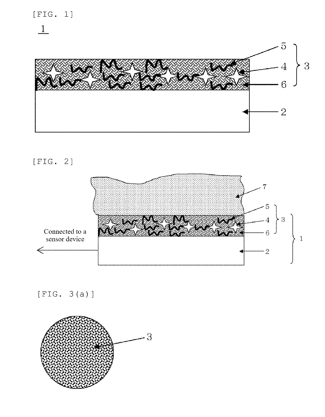
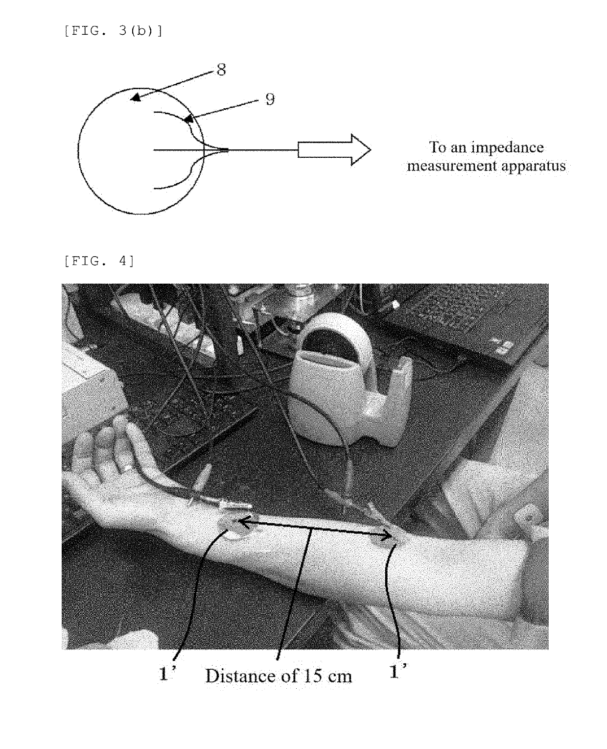
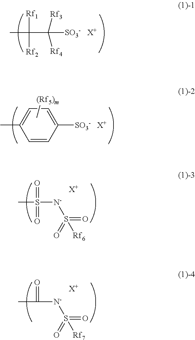
Bio-electrode composition, bio-electrode, and method for manufacturing a bio-electrode
a bioelectrode and composition technology, applied in the direction of non-metal conductors, applications, conductors, etc., can solve the problems of loss of electric conductivity, skin allergies, and use of electro-conductive polymers such as pedot-pss, and achieve excellent electric conductivity and biocompatibility. excellent, free from the risk of allergic reactions
- Summary
- Abstract
- Description
- Claims
- Application Information
AI Technical Summary
Benefits of technology
Problems solved by technology
Method used
Image

Examples
example
[0143]Hereinafter, the present invention will be specifically described by giving Examples and Comparative Examples, but the present invention is not limited thereto.
[0144]Ionic polymers 1 to 17 blended to solutions of bio-electrode composition as an electro-conductive material were synthesized as follows. Each 30 mass % monomer solution in PGMEA was introduced into a reaction vessel and mixed. The reaction vessel was cooled to −70° C. under a nitrogen atmosphere, and subjected to vacuum degassing and nitrogen blowing repeated for three times. After raising the temperature to room temperature, azobisisobutyronitrile (AIBN) was added thereto as a polymerization initiator in an amount of 0.01 mole per 1 mole of the whole monomers, this was warmed to a temperature of 60° C. and then allowed to react for 15 hours. The composition of obtained polymer was determined by 1H-NMR after drying the solvent, and the Mw and Mw / Mn were determined by gel permeation chromatography (GPC) using tetrah...
examples 1 to 19
, Comparative Examples 1 to 3
[0168]On the basis of each composition described in Tables 1 and 2, the ionic polymer, the hydroxy group-containing compound(s), and the additive (electric conductivity improver) were mixed and degassed, and the isocyanate compound(s) was mixed thereto at the end to prepare each bio-electrode composition solution (Bio-electrode composition solutions 1 to 19, Comparative bio-electrode composition solutions 1 to 3).
TABLE 1Bio-Electro-Hydroxy group-containingIsocyanateAdditiveelectrodeconductivecompoundscompound(partscompositionmaterial(parts by mass)(parts by mass)by mass)solution(parts bymass)Bio-IonicHydroxy silicone compound 1 (5)IsocyanateCarbonelectrodepolymer 1Hydroxy compound 1 (1)compound 1 (4)blackcomposition(4)Hydroxy compound 2 (0.5)(2)solution 1Hdroxy compound 4 (10)Bio-IonicHydroxy silicone compound 2 (5)IsocyanateCarbonelectrodepolymer 2Hydroxy compound 3 (0.2)compound 2 (2.6)blackcomposition(4)Hydroxy compound 5 (10)(2)solution 2Bio-IonicHyd...
PUM
| Property | Measurement | Unit |
|---|---|---|
| temperature | aaaaa | aaaaa |
| thickness | aaaaa | aaaaa |
| thickness | aaaaa | aaaaa |
Abstract
Description
Claims
Application Information