Method for additive manufacturing porous inorganic structures and composites made therefrom

Inactive Publication Date: 2019-08-01
DOW GLOBAL TECH LLC
View PDF0 Cites 2 Cited by
  • Summary
  • Abstract
  • Description
  • Claims
  • Application Information

AI Technical Summary

Benefits of technology

[0012]The method surprisingly allows for the formation of an additive manufactured part that is highly porous. In addition, the thermoset material fails to flow during the heating to form the carbon (analogous to binder

Problems solved by technology

Because the technique requires melting of a filament and extrusion, the materials have been limited to thermoplastic polymers (typically nylon) and complex apparatus.
However, limited use of the technique has been used to fabricate ceramics or metals because of the difficulty in loading ceramics to high levels in the filaments yet still be able to melt and extrude the thermoplastic polymer and because of the difficulty to fabricate greenware (parts after the thermoplastic polymer has been

Method used


Image

  • Method for additive manufacturing porous inorganic structures and composites made therefrom
  • Method for additive manufacturing porous inorganic structures and composites made therefrom

Examples


Example

Example 1

[0077]30 grams of the prepolymer and 10 grams of ELFTEX™ S7100 Carbon Black (carbon black filler) (39% volume) available from Cabot Corp. were mixed at 2000 RPM for 2 minutes using a DAC 400 Speed Mixer (FlackTek Inc, Landrum S.C.) to form a printable mixture. Then, 0.35 g catalyst 2,2′-dimorpholinodiethylether (DMDEE) was added and the formulation mixed for 2 more minutes. The filler had a OAN of about 117 cc / 100 g and Iodine number of 189 mg / g. The material was then transferred into a plastic bag, and extruded into a 10 cc syringe barrel, plugged with a white Smoothflow piston, and capped with an EFD snap-on endcap, all purchased from Nordson Corporation, Westlake Ohio.

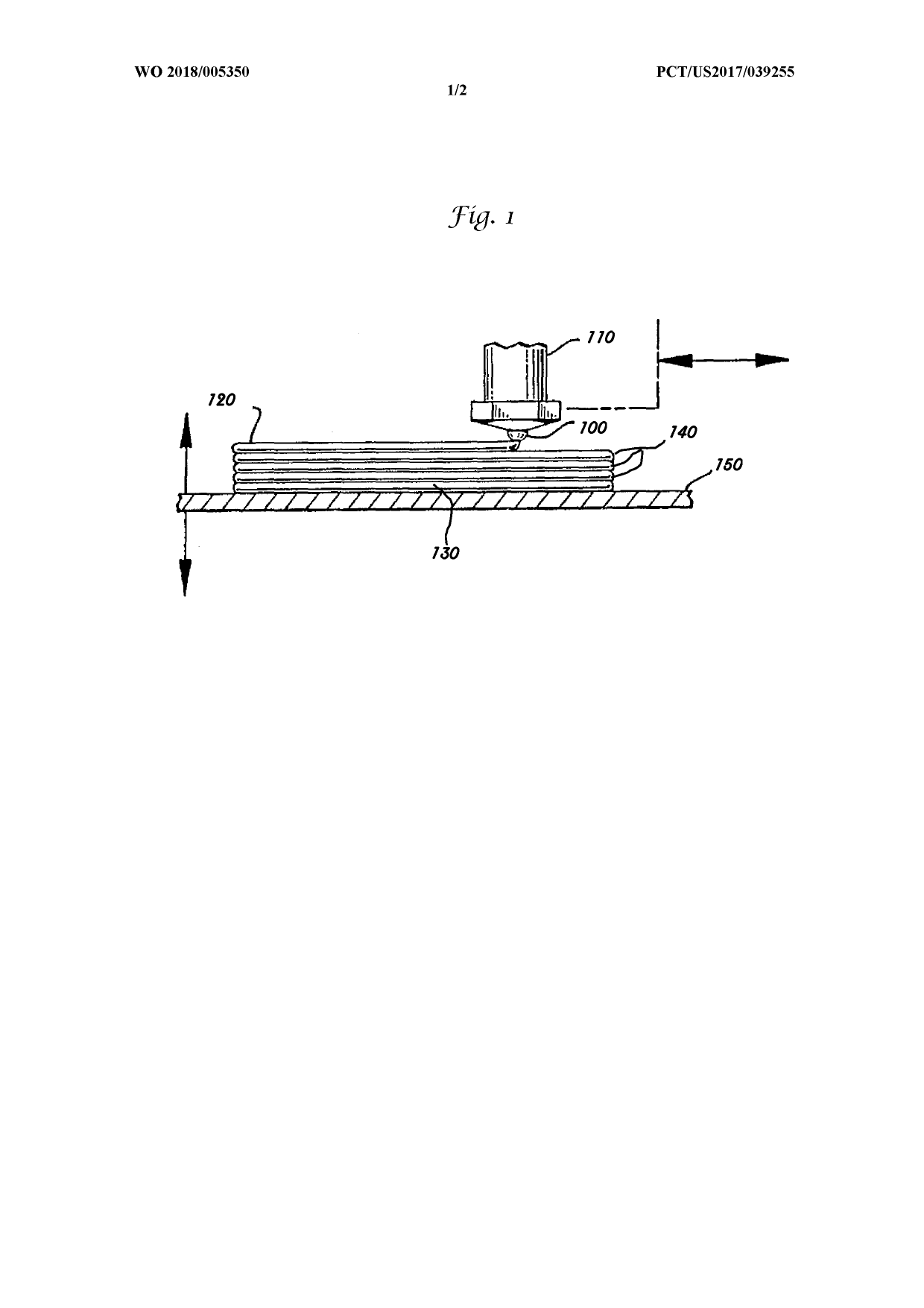
[0078]A high pressure dispensing tool, Nordson HP4X, Nordson Corporation, Westlake Ohio, was mounted on an UltraTT EFD automated dispensing system, (Nordson Corporation, Westlake Ohio) which acts as a programmable XYZ stage. The filled syringe was loaded into the dispenser and the material pushed through a ...

Example

Example 2

[0080]Example 1 was repeated except that the printable mixture was comprised of 14% by volume carbon black filler, 30% of copper powder (Product #41205, Alfa Aesar, Haverhill, Mass., 0.5-1.5 μm) with the balance being the prepolymer and catalyst. The printable mixture was printed, cured and pyrolyzed in the same manner as in Example 1. A porous copper, carbon black composite bound by a carbon binding phase was formed, which retained the shape of the cured additive manufactured part. This porous inorganic body was further heated in air to 900° C. in air in the same manner as the nitrogen heat treatment of Example 1. A porous copper oxide body was formed.

Example

Example 3

[0081]Example 2 was repeated except that the printable mixture was comprised of 16.9% by volume carbon black filler, 32.9% of silicon powder (Product # US1121, US Research Nanomaterials, Houston, Tex., 1-3 μm with the balance being the prepolymer and catalyst. The printable mixture was printed, cured and pyrolyzed in the same manner as in Example 2. A porous silicon, carbon black composite bound by a carbon binding phase was formed, which retained the shape of the cured additive manufactured part. This porous inorganic body was further heated in air to 900° C. in air as in Example 2. A porous silicon dioxide body was formed.


PUM

PropertyMeasurementUnit
Porosityaaaaaaaaaa
Exposure limitaaaaaaaaaa

Abstract

A porous inorganic additive manufactured article that is comprised of at least two layers of inorganic particulates bound together by a carbon binding phase throughout. The additive manufactured article may be formed by additive manufacturing using a mixture comprised of an organic reactive material and inorganic particulates, wherein the organic reactive material is subsequently reacted to form a thermoset material that forms carbon upon heating that binds the inorganic particulates together to form the porous inorganic additive manufactured article. The porous inorganic additive manufactured article may then be infiltrated with a liquid that is solidified to form a composite article or may be further heated in a differing atmosphere to form a further sintered or reacted porous inorganic article.

Description

FIELD OF THE INVENTION[0001]The invention relates to a method of additive manufacturing of porous inorganic structures and composite articles made using the porous structures. In particular, the invention is an additive manufacturing method for forming porous inorganic structures bound together by a carbon phase.BACKGROUND OF THE INVENTION[0002]Fused filament fabrication (FFF), which is also commonly called plastic jet printing or fused deposition modeling (FDM) has been used to form 3D parts by using thermo-plastic filaments that are drawn into a nozzle, heated, melted and then extruded where the extruded filaments fuse together upon cooling (see, for example, U.S. Pat. Nos. 5,121,329 and 5,503,785). Because the technique requires melting of a filament and extrusion, the materials have been limited to thermoplastic polymers (typically nylon) and complex apparatus. In addition, the technique has required support structures that are also extruded when making complex parts that must s...

Claims


Application Information

Patent Timeline
IPC IPC(8): C04B35/524B29C64/165B29C64/118B33Y10/00B33Y70/00B33Y40/00B28B1/00C04B35/634C04B35/638C04B35/64C04B41/00C04B41/48C04B41/83C04B35/657
CPCC04B35/524B29C64/165B29C64/118B33Y10/00B33Y70/00B33Y40/00B28B1/001C04B35/63456C04B35/638C04B35/64C04B41/009C04B41/4853C04B41/83C04B35/657B29K2101/10B29K2105/0002C04B2235/48C04B2235/424C04B2235/3281C04B2235/3418C04B2235/3232C04B2235/3258C04B2235/3463C04B2235/6026C04B2235/616B32B18/00C04B35/532C04B38/0022C04B38/067C04B2111/00612C04B2235/422C04B35/14C04B35/185C04B35/45C04B35/46C04B35/495C04B35/553C04B35/5611C04B35/58014C04B35/6269C04B35/632C04B35/83C04B2235/3206C04B2235/3217C04B2235/3272C04B2235/407C04B2235/428C04B2235/5436C04B2235/6021C04B2235/652C04B2235/96B29C64/106C08G18/10C08G18/7671C08G18/4841C08G18/2081B33Y40/20B33Y70/10C08G18/307
Inventor PYZIK, ALEKSANDER JGORIN, CRAIG F.GOSS, JANET M.ALLEN, SHARONSOPHIEA, DANIEL P.
Owner DOW GLOBAL TECH LLC
Why Eureka
Try Eureka