
Hydrometallurgical process for nickel oxide ore

a technology of nickel oxide ore and hydrometallurgical process, which is applied in the direction of process efficiency improvement, etc., can solve the problems of increasing the number of equipment to increase cost and labor, increasing the cost of raw materials for metal smelting, and increasing so as to reduce the amount of final neutralized residue, reduce the amount of leach residue, and reduce the effect of facilities

Inactive Publication Date: 2019-12-19
SUMITOMO METAL MINING CO LTD
View PDF0 Cites 0 Cited by
  • Summary
  • Abstract
  • Description
  • Claims
  • Application Information

AI Technical Summary

Benefits of technology

The hydrometallurgical process for recycling nickel and cobalt from high pressure acid leach processes for nickel oxide ores presents a solution to common problems of conventional processes. The process helps to separate and recover chromite particles from the slurry, reducing wear on equipment and minimizing residue. Additionally, the process separates and recovers hematite from the leach residue, reducing the amount of residue and lowering environmental risks while providing a valuable resource.

Problems solved by technology

In recent years, raw material cost for metal smelting has significantly increased with the further progress of oligopolization of mining rights for mineral resources, such as coal, iron, copper, nickel, cobalt, chromium, and manganese.
Therefore, also in metal smelting, technical development has been made, as a measure for cost reduction, for using a low-grade raw material which has not been used since it is disadvantageous in terms of cost.
However, there have been problems in that the two-stage leaching has increased the number of equipment to increase cost and labor, and a large amount of dilute solution produced in the washing of the leach residue has required cost.
However, the practical plant using this method will have the following problems.
A first problem is the wear of facilities, which is required to be suppressed.
The wear of the materials of facilities is significantly accelerated by the conveyed slurry, and especially the frequency of maintenance of the facilities such as piping and pumps in the leaching step is high, which greatly causes an increase in maintenance cost and a reduction in the rate of plant operation.
A second problem is the amount of the final neutralized residue, which is required to be reduced.
Therefore, the final neutralized residue cannot be recycled, and the construction and the maintenance of the tailings dam have been a heavy cost burden.

Method used


Image

  • Hydrometallurgical process for nickel oxide ore
  • Hydrometallurgical process for nickel oxide ore
  • Hydrometallurgical process for nickel oxide ore

Examples


example 1

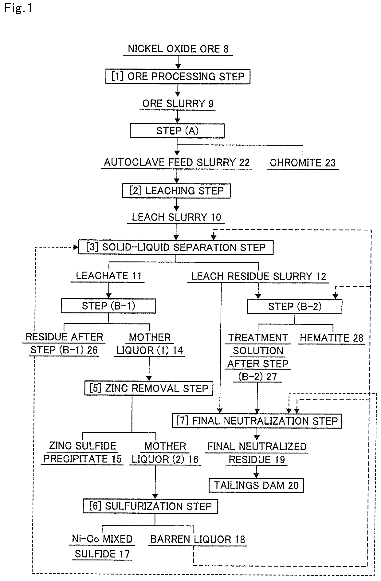
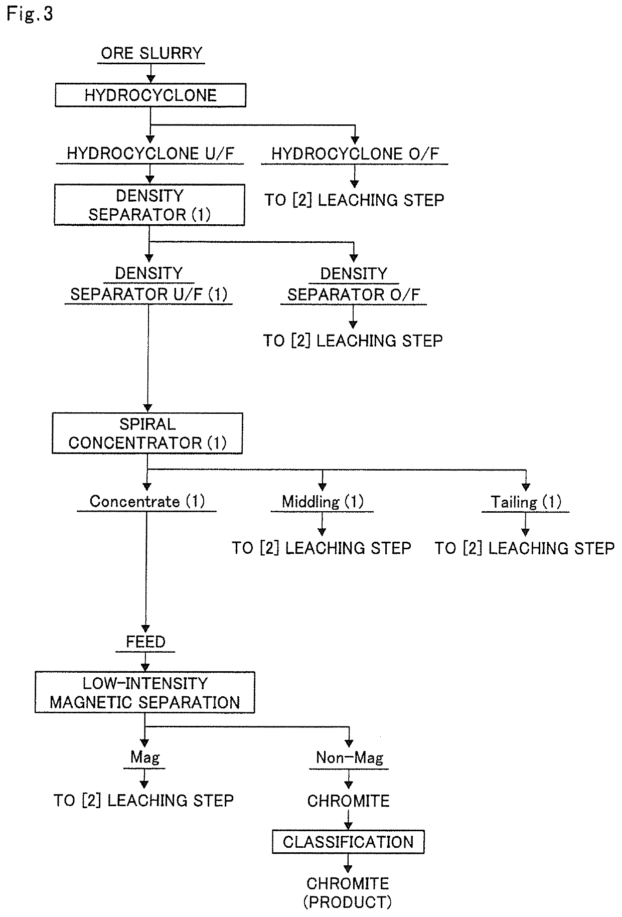
[0188]In the production flow of the present invention in FIG. 1, the ore slurry 9 was subjected to step (A) according to the execution flow chart shown in FIG. 3, in which the ore slurry was subjected to classification with a hydrocyclone to separate goethite and then subjected to specific gravity separation once with a density separator and a spiral concentrator in combination in this order.

[0189]The ore slurry having the composition shown in Table 3 was classified using a hydrocyclone (manufactured by Daiki Ataka Engineering Co., Ltd., Model MD-9) as a classifier used in step (A).

[0190]In Example 1, the classification was performed under the conditions of a slurry concentration of 15% by weight, a slurry temperature of normal temperature, and an operating pressure of 0.2 MPa.

[0191]The ore slurry composition and the composition of the underflow from the hydrocyclone (hydrocyclone U / F) are shown together in Table 3. Note that the unit in the following tables is % by weight.

TABLE 3Cr...

example 2

[0223]In the production flow of the present invention in FIG. 1, the ore slurry was subjected to step (A) as shown in the execution flow chart of step (A) in FIG. 4, in which the ore slurry was subjected to specific gravity separation repeatedly twice with a density separator and then subjected to specific gravity separation with a spiral concentrator.

[0224]First, the ore slurry having the composition shown in Table 9 was classified using a hydrocyclone (manufactured by Daiki Ataka Engineering Co., Ltd., Model MD-9) as a classifier used in step (A).

[0225]In Example 2, the classification was performed under the conditions of a slurry concentration of 15% by weight, a slurry temperature of normal temperature, and an operating pressure of 0.2 MPa.

[0226]The ore slurry composition and the composition of the hydrocyclone U / F are shown together in Table 9. Note that the unit in the following tables is % by weight.

TABLE 9Cr2O3SiO2FeNiOre slurry2.54.451.51.2Hydrocyclone U / F13.56.045.20.8Unit...

example 3

[0269]The overflow of the hydrocyclone and the overflow of the density separator in Example 1 were charged into an autoclave at a solid weight ratio of 77:15, and thereto was added 98% sulfuric acid. The resulting mixture was subjected to high pressure acid leach under the following conditions to produce a leach slurry 10.

[0270]Further, the produced leach slurry was separated into a leachate 11 and a leach residue slurry 12 by a solid-liquid separation step.

[Leaching Conditions]

[0271]Leaching temperature: 245° C.

[0272]Leaching time: 60 minutes

[0273]Final (at the completion of leaching) free sulfuric-acid concentration: 40 [g / L]

[0274]Slurry concentration: 30% by weight

[0275]Autoclave volume: 5 L

[0276]Next, in order to know the Cr2O3 grade in the leach residue slurry 12, Mg(OH)2 slurry having a concentration of 20% by weight as a neutralizing agent was added to the leach residue slurry 12 to neutralize the leach residue slurry so that it might have a pH of 2.5 at 70° C.

[0277]Next, the...


PUM

PropertyMeasurementUnit
temperatureaaaaaaaaaa
pHaaaaaaaaaa
particle sizeaaaaaaaaaa

Abstract

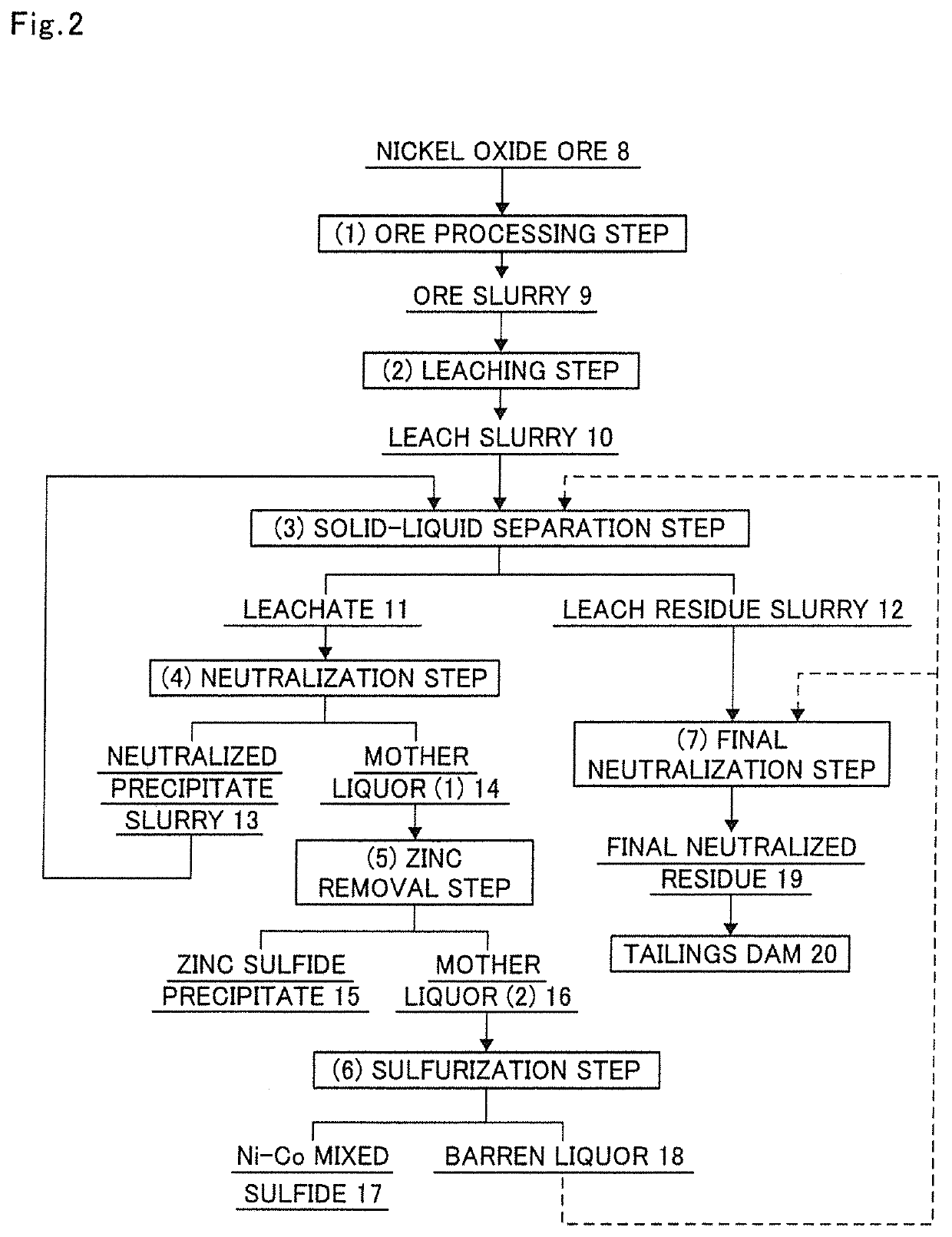
Provided is a hydrometallurgical process for nickel oxide ore for recovering nickel and cobalt using a high pressure acid leach process, the process achieving simplification and durability improvement of production facilities, achieving cost reduction and suppression of environmental risk by the compression of the capacity of a tailings dam for storing wastes, and being capable of recycling and effectively utilizing the wastes as a resource. The hydrometallurgical process for nickel oxide ore for recovering nickel and cobalt using a high pressure acid leach process includes an ore processing step, a leaching step, a solid-liquid separation step, a neutralization step, a zinc removal step, a sulfurization step, and a final neutralization step, and further includes step (A), or further includes step (A) and, step (B-1) and / or step (B-2) after step (A).

Description

[0001]The present application is a divisional application of U.S. patent application Ser. No. 15 / 304,898, filed Oct. 18, 2016, the contents of which are hereby incorporated by reference in their entirety.BACKGROUND1. Field of the Invention[0002]The present invention relates to a hydrometallurgical process for nickel oxide ore, specifically relates to a hydrometallurgical process for nickel oxide ore for recovering nickel and cobalt from nickel oxide ore using a high pressure acid leach process including an ore processing step, a leaching step, a solid-liquid separation step, a neutralization step, a zinc removal step, a sulfurization step, and a final neutralization step, in which problems are solved by suppressing the wear, caused by an ore slurry produced from the ore processing step, of facilities such as conveyance piping and a pump for conveying the ore slurry and improving the durability of the facilities to thereby reduce the amount of a final neutralized residue produced fro...

Claims


Application Information

Patent Timeline
Patent Type & Authority Applications(United States)
IPC IPC(8): C22B3/00C22B3/44C22B3/22C22B3/08C22B1/24
CPCC22B23/0461C22B3/22C22B23/043C22B1/24C22B3/08C22B3/44C22B23/0415C22B23/005Y02P10/20
Inventor OHARA, GOKAN, YASUMASAIMAMURA, MASAKI
Owner SUMITOMO METAL MINING CO LTD
Learn More