
Encapsulated flexible electronics for long-term implantation

a flexible electronics and long-term implantation technology, applied in the field of encapsulated flexible electronics for long-term implantation, can solve the problems of corresponding functional degradation, inability to reliably withstand electronic devices without damage, etc., and achieve the effect of beneficial long-term implantation characteristics

Active Publication Date: 2020-01-23
THE BOARD OF TRUSTEES OF THE UNIV OF ILLINOIS +1
View PDF0 Cites 15 Cited by
  • Summary
  • Abstract
  • Description
  • Claims
  • Application Information

AI Technical Summary

Benefits of technology

The patent text discusses methods and devices for making electronic devices with a high quality encapsulation layer. The methods can provide electronic devices with long-term resistance to water permeation and good mechanical properties without sacrificing device flexibility, bendability, and stretchability. The methods can be used for long-term biological implants. The decoupling of the encapsulation layer from the electronic device processing onto the first encapsulation layer provides a number of functional benefits, such as achieving maximum quality of the encapsulation layer, obtaining low defect number, and achieving good mechanical properties. The method also allows for relatively thin layers in the device, such as encapsulation layers and electronic devices, and achieving good mechanical properties, including stretchability, bendability, foldability, compliance, conformability, and the like. The patent also describes a method of making liquid and liquid vapor-proof material by providing substrates with encapsulating layers and covering the material provided onto one of the encapsulating layers with the other encapsulating layer. The encapsulating layers are substantially defect free so that liquid or liquid vapor is prevented from passing through each of the encapsulating layers.

Problems solved by technology

For example, processing of the encapsulation layer may involve high temperatures that electronic devices cannot reliably withstand without damage and corresponding functional degradation.

Method used


Image

  • Encapsulated flexible electronics for long-term implantation
  • Encapsulated flexible electronics for long-term implantation
  • Encapsulated flexible electronics for long-term implantation

Examples


example 1

, Transferred Layers of Thermally Grown Silicon Dioxide as Biofluid Barriers for Biointegrated Flexible Electronic Systems

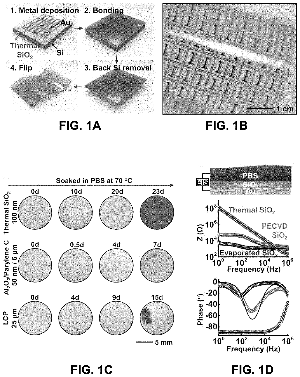
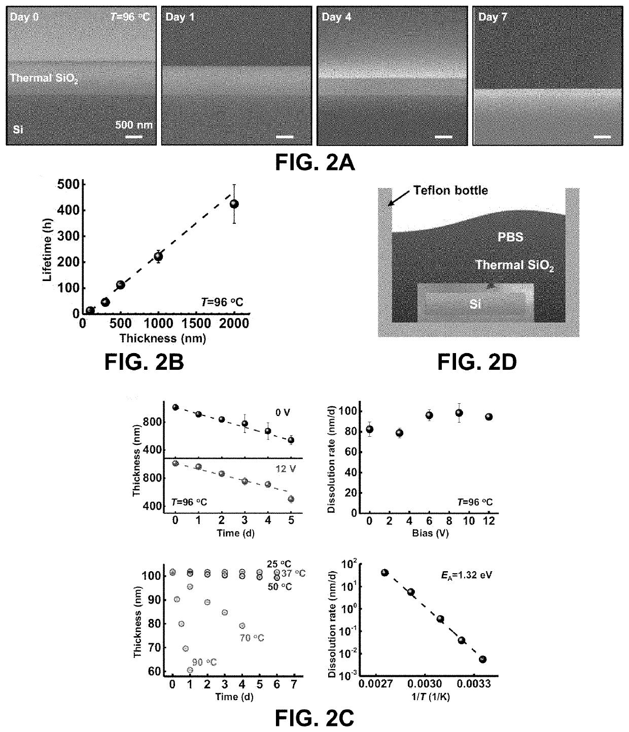
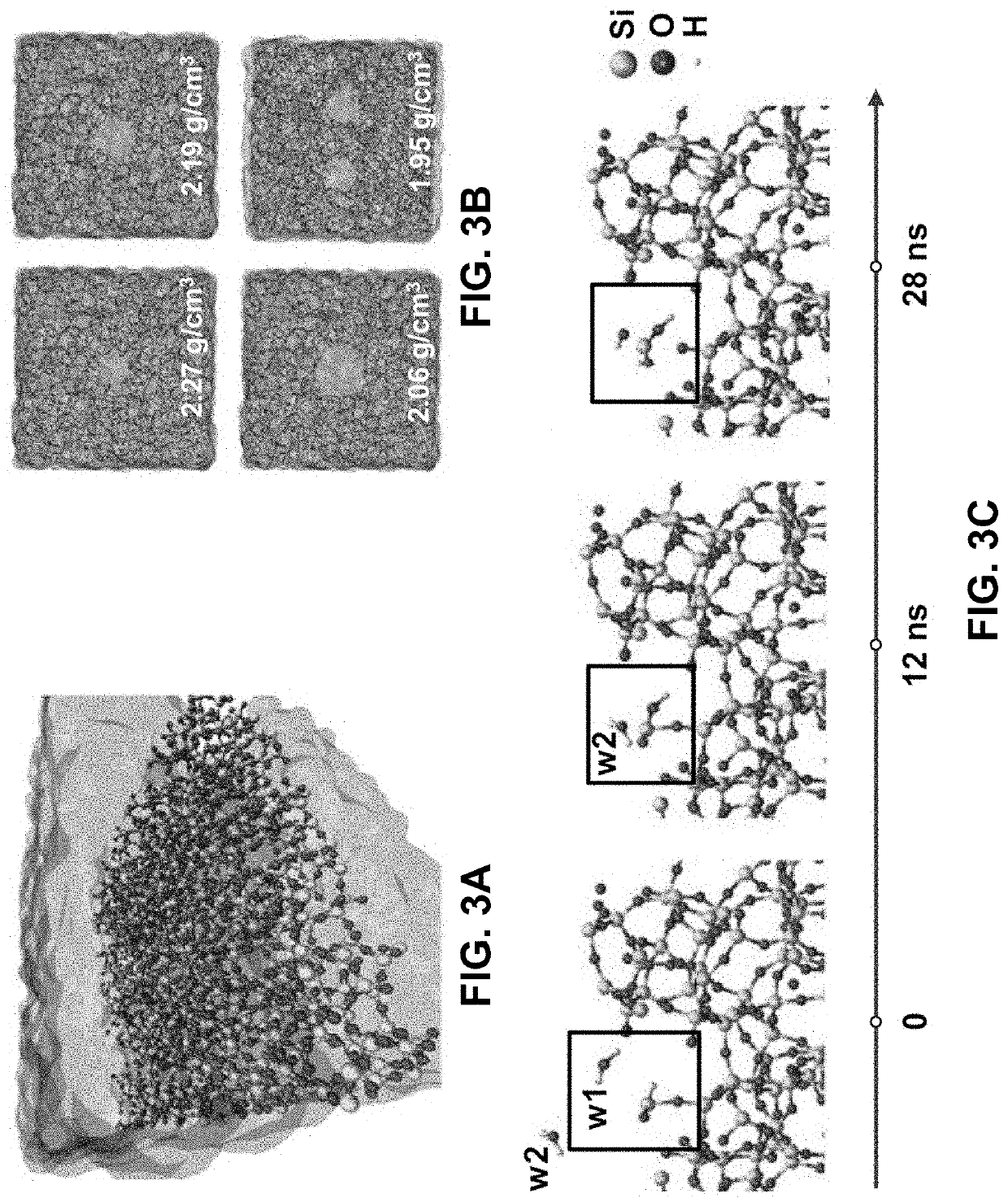
[0119]Materials that can serve as long-lived barriers to biofluids are essential to the development of any type of chronic electronic implant. Devices such as cardiac pacemakers and cochlear implants use bulk metal or ceramic packages as hermetic enclosures for the electronics. Emerging classes of flexible, biointegrated electronic systems demand similar levels of isolation from biofluids but with thin, compliant films that can simultaneously serve as biointerfaces for sensing and / or actuation while in contact with the soft, curved, and moving surfaces of target organs. This example introduces a solution to this materials challenge that combines (i) ultrathin, pristine layers of silicon dioxide (SiO2) thermally grown on device-grade silicon wafers, and (ii) processing schemes that allow integration of these materials onto flexible electronic platforms. Accelerate...

example 1 references

[0139]1. Kim D-H, et al. (2011) Epidermal electronics. Science 333(6044):838-843.[0140]2. Lipomi D J, et al. (2011) Skin-like pressure and strain sensors based on transparent elastic films of carbon nanotubes. Nat Nanotechnol 6(12):788-792.[0141]3. Xu S, et al. (2014) Soft microfluidic assemblies of sensors, circuits, and radios for the skin. Science 344(6179):70-74.[0142]4. Gao W, et al. (2016) Fully integrated wearable sensor arrays for multiplexed in situ perspiration analysis. Nature 529(7587):509-514.[0143]5. Wu W, et al. (2014) Piezoelectricity of single-atomic-layer MoS2 for energy conversion and piezotronics. Nature 514(7523):470-474.[0144]6. McAlpine M C, Ahmad H, Wang D, Heath J R (2007) Highly ordered nanowire arrays on plastic substrates for ultrasensitive flexible chemical sensors. Nat Mater 6(5):379-384.[0145]7. Kaltenbrunner M, et al. (2013) An ultra-lightweight design for imperceptible plastic electronics. Nature 499(7459):458-463.[0146]8. Lochner C M, Khan Y, Pierre...

example 2

ely Coupled Arrays of Multiplexed Flexible Silicon Transistors for Long-Term Cardiac Electrophysiology

[0225]Advanced capabilities in electrical recording are essential for the treatment of heart-rhythm diseases. The most advanced technologies use flexible integrated electronics; however, the penetration of biological fluids into the underlying electronics and any ensuing electrochemical reactions pose significant safety risks. Here, we show that an ultrathin, leakage-free, biocompatible dielectric layer can completely seal an underlying array of flexible electronics while allowing for electrophysiological measurements through capacitive coupling between tissue and the electronics, without the need for direct metal contact. The resulting current-leakage levels and operational lifetimes are, respectively, four orders of magnitude smaller and between two and three orders of magnitude longer than those of other flexible-electronics technologies. Systematic electro physiological studies ...


PUM


Abstract

Provided are methods of making a long-term implantable electronic device, and related implantable devices, including by providing a substrate having a first encapsulation layer that covers at least a portion of the substrate, the first encapsulation layer having a receiving surface; providing one or more electronic devices on the first encapsulation layer receiving surface; and removing at least a portion of the substrate from the first encapsulation layer; thereby making the long-term implantable electronic device. Further desirable properties, including device lifetime increases during use in environments that are challenging for sensitive electronic device components, are achieved through the use of additional layers such as longevity-extending layers and / or ion-barrier layers in combination with an encapsulation layer.

Description

CROSS-REFERENCE TO RELATED APPLICATIONS[0001]This application claims the benefit of U.S. Provisional Patent Application Nos. 62 / 573,533 filed Oct. 17, 2017 and 62 / 738,608 filed Sep. 28, 2018, each of which is specifically incorporated by reference to the extent not inconsistent herewith.STATEMENT REGARDING FEDERALLY SPONSORED RESEARCH OR DEVELOPMENT[0002]This invention was made with government support under HR0011-14-C-0102 awarded by the Defense Advanced Research Projects Agency (DARPA). The government has certain rights in the invention.BACKGROUND OF INVENTION[0003]A fundamental problem encountered by use of flexible electronics for chronic implantation in biological systems is the need for thin-film barriers to biofluids with multi-decade lifetimes. Various materials proposed as biofluid barriers in the art are unsuitable for a range of reasons. First, to achieve reliable long-term water impermeability, conventional materials must be relatively thick, thereby impacting the abilit...

Claims


Application Information

Patent Timeline
IPC IPC(8): A61B5/042H01L21/02A61B5/046A61N1/05A61B5/03A61B5/361
CPCH01L21/02181A61B5/042H01L21/02167G01N27/414A61B5/046A61N1/0587H01L21/02282H01L21/02115H01L21/02118H01L21/02258A61B5/031H01L21/02271H01L21/02178H01L21/02164A61N1/3758A61N1/37512A61N1/37514H01L23/3121A61B5/283A61B5/333A61B5/361
Inventor ROGERS, JOHN A.FANG, HUIZHAO, JIANINGSONG, ENMINGLEE, YOON KYEUNG
Owner THE BOARD OF TRUSTEES OF THE UNIV OF ILLINOIS
Learn More