Combined osmotic and hydrogel cervical dilators and method of making same

a cervical dilator and hydrogel technology, which is applied in the field of combined osmotic and hydrogel cervical dilators and making same, can solve the problems of reversible dehydration of tissue, and affecting the effect of osmotic and hydrogel dilators. , to achieve the effect of reducing the risk of osmotic and hydrogel dilating, reducing the risk o

Active Publication Date: 2020-02-06
MEDICEM TECH SRO
View PDF0 Cites 1 Cited by
  • Summary
  • Abstract
  • Description
  • Claims
  • Application Information

AI Technical Summary

Benefits of technology

[0010]In addition, a method of manufacturing this cervical dilator is described herein. The method includes providing a hydrogel in a partly or fully dehydrated state, and axially stretching the hydrogel at a temperature above the glass transition temperature of the water-insoluble synthetic hydrophilic polymer, thereby producing the stem comprising the partly or fully dehydrated hydrogel, and achieving the capability of radial expansion. Then, the stem comprising the partly or fully dehydrated hydrogel is subsequently cooled under the axial stress to an ambient temperature.
[0011]Furthermore, an additional method of manufacturing this cervical dilator is described herein. The method includes providing a hydrogel in a hydrated state, and axially stretching the hydrogel and maintaining a predetermined length of the hydrogel while drying the hydrogel, thereby producing the stem comprising the partly or fully dehydrated hydrogel, and achieving the capability of radial expansion.

Problems solved by technology

The mechanical pressure generated by these devices partly and reversibly dehydrates the tissue that thus becomes softer and more deformable.
However, the maximum rate of the partial dehydration generated by the mechanical pressure is controlled by hydraulic permeability of cell walls, and draining of water from the tissue takes some time.
Consequently, mechanical dilators force tissue to expand faster than the dehydration rate allows, and this may cause rupture of cell membranes and consequent tissue damage, even scarring.
However, the dilatation rate is still not controlled easily, and thus may easily exceed the safe limit derived from the drainage rate of bodily fluids from the tissue.
These devices work on purely osmotic principle since the hydrogel sponge used as the salt carrier is inherently soft and cannot generate any significant mechanical pressure against the tissue.
However, dilators from LJ have various disadvantages: the hydration is relatively slow and rather irregular, the shape and geometry of the dried stems is rather irregular, osmotic pressure is relatively low, mechanical expansion against the pressure of stiff cervical tissue (e.g., in the internal os) may be limited, the mechanical strength in the state of maximum hydration may be too low to prevent disintegration, sterilization of the product may be uncertain and there is no design feature or property that would prevent multiple use and thus decrease the risk of infection.

Method used


Image

  • Combined osmotic and hydrogel cervical dilators and method of making same
  • Combined osmotic and hydrogel cervical dilators and method of making same

Examples


example 1

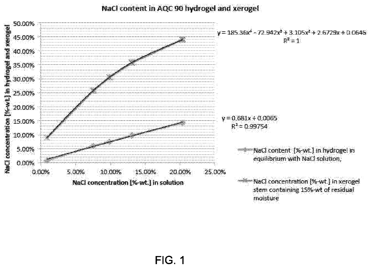
[0049]A hydrogel for the cervical dilator was prepared according to U.S. Pat. No. 6,232,406, which is incorporated herein by reference in its entirety. PAN of weight average molecular weight of 200,000 g / mol was dissolved in 55%-wt. NaSCN aqueous solution to form a 10%-wt. polymer solution. NaOH dissolved in 55%-wt. NaSCN aqueous solution was added at ambient temperature in an amount required for the PAN / NaOH mass ratio to be 1:10. Then, the solution was transferred into a jacketed tubular reactor, where it was heated to 70° C. for 60 hours. The resulting solution of the multi-block acrylic copolymer was cooled to 40° C. and transferred into a pressure vessel from where it was fed by a pressurized gas to a metering pump with a progressing cavity rotor. The solution was extruded through a cooled nozzle into a coagulation bath filled with NaSCN aqueous solution having an NaSCN concentration from 1 to 5%-wt. The coagulated hydrogel rod was washed until substantially all of the NaSCN wa...

example 2

[0054]Hydrogels prepared according to Example 1 were soaked with 10%-wt. aqueous solutions of the following monomers:[0055]1. sodium acrylate[0056]2. methacryloyloxypropane-1-sulfonic acid[0057]3. 4-vinylphenyl sulfuric acid[0058]4. vinylphosphonic acid.

[0059]After equilibrium was reached in each solution, the monomer-soaked hydrogel rods were stretched on drying racks similarly as in Example 1, and dried at 80° C. for 18 hours. Although no initiator was used and drying was performed in the presence of air, all monomers polymerized and an interpenetrating network of a polyelectrolyte within the multiblock copolymer hydrogel was formed. When swelled in isotonic solution, no elution of the polyelectrolyte was observed, because it is apparently firmly anchored within the hydrogel structure.

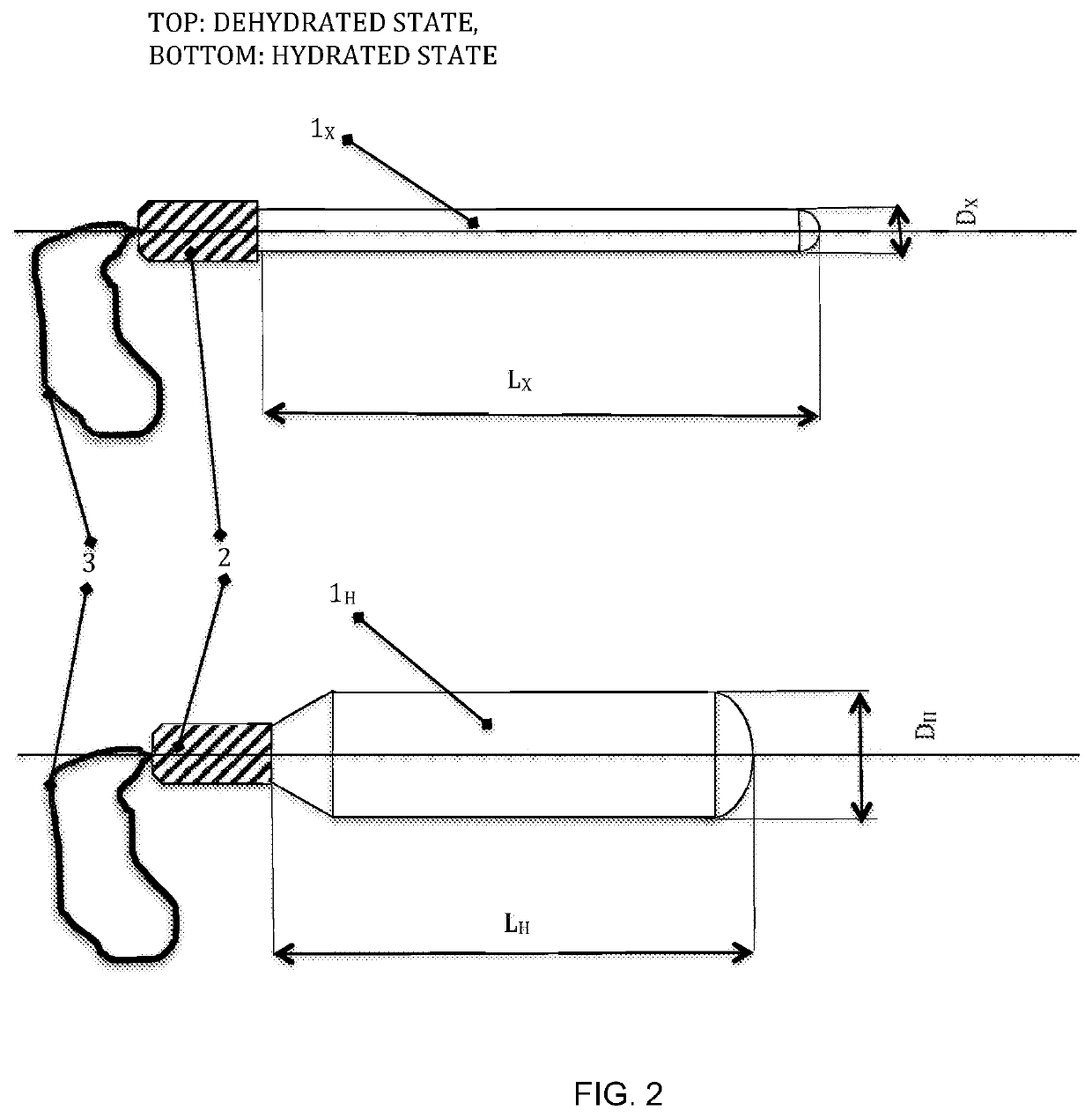
[0060]The xerogel stems could then be equipped with glued-on plastic handles and sterilized by irradiation or by a gas. FIG. 2 shows a cervical dilator in a dehydrated state (top drawing) and in a hy...

example 3

[0062]The hydrogel interpenetrating network from Example 2 with the poly(methacryloyloxypropane-1-sulfonic acid) monomer was soaked with excess of aqueous solution containing 5%-wt. of sodium sulfate, 3%-wt. of 1,2-propyleneglycol and 1%-wt. of tri-ethanol amine. Then, it was dried under radial tension at 70° C. until the residual water content reached approximately 18%-wt. Then, the product was cut to size, trimmed, equipped with handles and sealed in the sterilization pouches as in previous examples. The cervical dilator device was sterilized by electron beam at 40 kGy. This cervical dilator device provides for a fast cervix ripening with strong radial expansion and the capability to be shaped prior to insertion to fit any particular geometry of cervical canal.


PUM

PropertyMeasurementUnit
temperatureaaaaaaaaaa
diameteraaaaaaaaaa

Abstract

A cervical dilator including a stem comprising a partly or fully dehydrated hydrogel comprising a water-insoluble synthetic hydrophilic polymer capable of radial expansion due to absorption of water from a bodily fluid. The cervical dilator softens and ripens the cervical tissue and expands the cervical canal by a combined action of radial hydrogel stem expansion and osmotic withdrawal of water from the tissue. The osmotic withdrawal is caused by at least one osmotically active compound, such as a water-soluble salt, a polyelectrolyte, or a mixture thereof, wherein the at least one osmotically active compound is dispersed in the hydrogel. The cervical dilator may also include a non-toxic plasticizer of the hydrogel, such as water.

Description

CROSS-REFERENCE TO RELATED APPLICATIONS[0001]This application claims priority to U.S. Provisional Patent Application No. 62 / 404,997, filed Oct. 6, 2016. The disclosure of which is incorporated herein by reference.FILED OF THE INVENTION[0002]The present invention relates to cervical dilators, and methods of manufacturing cervical dilators.BACKGROUND OF THE INVENTION[0003]Tissue expansion is used in a variety of surgical procedures. The tissue expansion can be either temporary or permanent. One well-known example of temporary expansion is dilatation of the cervical canal in gynecology. It is achieved naturally during childbirth, but it can also be achieved artificially by various means, such as by administration of prostaglandins (see M J Keirse, Prostaglandins in preinduction cervical ripening. Meta-analysis of worldwide clinical experience, The Journal of reproductive medicine (1993) 38: 89-100). The cervical canal can also be temporarily expanded in response to a short-term radial ...

Claims


Application Information

Patent Timeline
Patent Type & Authority Applications(United States)
IPC IPC(8): A61M29/02A61B17/00A61L31/14
CPCA61B17/00A61B2017/00898A61B2017/00942A61B2017/00893A61L31/145A61M29/02A61B2017/4225A61L31/14A61P15/00A61B17/42A61B90/02A61M2210/1433B29C55/005B29C37/0092A61M2207/00A61M2205/0216
Inventor STOY, VLADIMÍRDRUNECKÝ, TOMASDUDIC, MIROSLAVSTEHLICEK, PETRVOKOUNOVA, ZDENKA
Owner MEDICEM TECH SRO
Why Eureka
Try Eureka