
Ion-Doped Two-Dimensional Nanomaterials

Active Publication Date: 2020-03-26
NORTHEASTERN UNIV
View PDF0 Cites 1 Cited by
  • Summary
  • Abstract
  • Description
  • Claims
  • Application Information

AI Technical Summary

Benefits of technology

The invention provides new methods for making ion-doped two-dimensional nanomaterials and devices containing them. The materials have high carrier concentrations and can be easily fabricated without the need for electrodes or electrolytes. The methods allow for the adjustment of optical and electronic properties of the materials in a bias-free, electrode-free, and electrolyte-free manner. The materials can have selectable and tunable carrier concentrations and can be used in electronic devices such as diodes, transistors, and solar cells. The invention also provides a method for forming a p-n junction in a two-dimensional material. Overall, the invention provides new tools for research and development in the field of two-dimensional materials and devices.

Problems solved by technology

Doping of two-dimensional materials is more difficult, due to more limited opportunities to fit doping elements into the crystal lattice.
However, addition of passivation layers requires complex fabrication techniques, including a number of lithography steps, and the use of harsh conditions, and is also permanent.

Method used


Image

  • Ion-Doped Two-Dimensional Nanomaterials
  • Ion-Doped Two-Dimensional Nanomaterials
  • Ion-Doped Two-Dimensional Nanomaterials

Examples


example 1

Ion-Based Gating of Graphene.

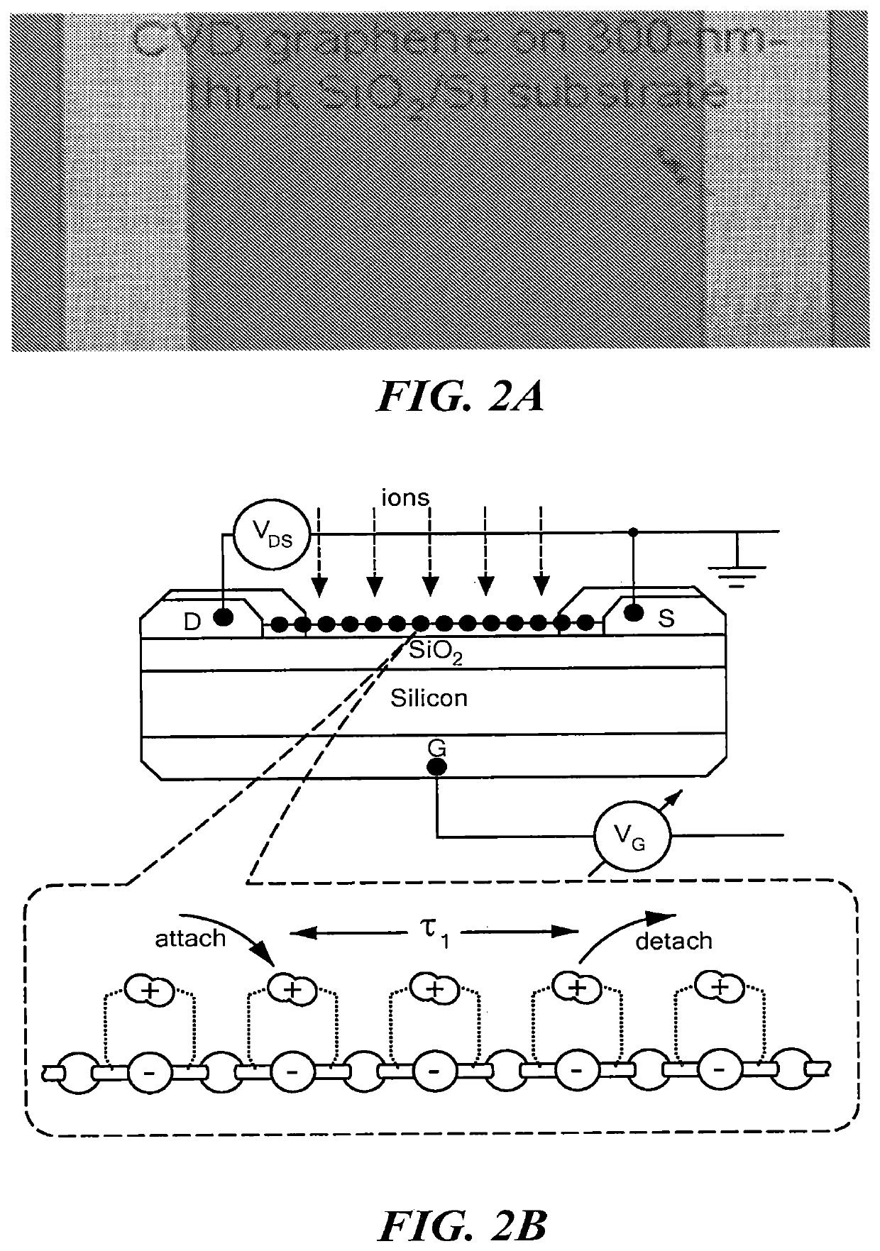
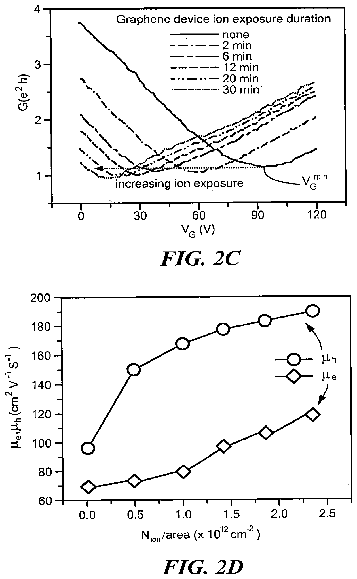
[0062]Ion-exposure experiments were performed on a variety of nanomaterials, both under vacuum (P˜10−5 Torr, using Granville Phillips Ionization Gauge Model No. 274003, producing primarily N2+) as well as in open air (Ion Projector Model No. NIP-6E), the generated ion flux was directed from the ionization gauge towards the device); both conditions were found to be equally effective. FIGS. 2A-2D outline the results of ion-incidence experiments on a gated, 3-terminal graphene device (shown in FIGS. 2A, 2B), in which the metal-graphene contact area was covered with a photoresist layer to eliminate any contact-induced effect. If the incident positive ions were to absorb electrons from graphene, they would induce holes (i.e. p-type doping) that should right-shift the transconductance curves towards higher positive values. In contrast (FIG. 2C), starting with an intrinsically p-doped device, the exposure to incident positive ions led to the curves being left-s...

example 2

Ion-Based Gating of Molybdenum Disulfide in an FET Device.

[0063]FIGS. 3A-3E summarize an experiment similar to Example 1 but performed on a monolayer MoS2 FET device. A monolayer of atomically thin MoS2 was made by chemical vapor deposition, resulting in an optoelectronic grade crystalline quality film. WO2016 / 133570 describes methods of making ultrathin MoS2 films. As in the previous case, the contact areas were protected with photoresist prior to ion-exposure. In this study, the devices were tested with both positive and negative ions. Different devices were used to eliminate any “history” effect. FIGS. 3C and 3D show how the transfer characteristics shifted to the left (indicating n-type doping in case of positive ions) and to the right (indicating p-type doping in case of negative ions). The transfer curves recovered (as seen in FIG. 3D) after overnight release, indicating that the ions did not form any chemical bonds. The induced carrier density was estimated using the formula ...

example 3

Stabilization of Ion-Doping by Addition of a Capping Layer.

[0064]Carrier-induction as demonstrated in Examples 1 and 2 remained effective as long as the ion source remained on, and stable doping levels could be achieved by controlling the source rate once the desired doping level had been achieved. However, while this approach was quite effective for investigating a variety of fundamental questions, for practical applications the doping effect must be stabilized.

[0065]Devices were capped with a freshly cured insulating polydimethylsiloxane (PDMS) thin film. FIGS. 4A-4E summarize the experimental results obtained where the release and recovery of the channel current in a set of devices using a single-wall carbon nanotube (SWNT) film; the devices were of similar geometry and resistance. The devices (shown in FIGS. 4A, 4B) were studied under various pressure and capping conditions over several days. In all devices, the channel current was monitored under a fixed bias (0.2V) after 2 min...


PUM

PropertyMeasurementUnit
Thicknessaaaaaaaaaa
Thicknessaaaaaaaaaa
Electric potential / voltageaaaaaaaaaa

Abstract

Ion-doped two-dimensional nanomaterials are made by inducing electronic carriers (electrons and holes) in a two-dimensional material using a captured ion layer at the surface of the material. The captured ion layer is stabilized using a capping layer. The induction of electronic carriers works in atomically-thin two-dimensional materials, where it induces high carrier density of at least 1014 carriers / cm2. A variety of novel ion-doped nanomaterials and p-n junction-based nanoelectronic devices are made possible by the method.

Description

CROSS REFERENCE TO RELATED APPLICATIONS[0001]This application claims the priority of U.S. Provisional Appl. No. 62 / 455,096, filed Feb. 6, 2017, which is hereby incorporated by reference in its entirety.STATEMENT REGARDING FEDERALLY SPONSORED RESEARCH OR DEVELOPMENT[0002]The invention was developed with financial support from Grant Nos. ECCS 1202376 and DMREF 1434824 from the National Science Foundation. The U.S. Government has certain rights in the invention.BACKGROUND[0003]Semiconductor materials require doping with chemical elements that promote altered electrical properties, such as the formation of holes and electrons to serve as electrical carriers. The availability of p-type and n-type doping leads to the ability to form p-n junctions, which form the basis of a wide variety of semiconductor devices such as transistors and diodes needed in logic circuits and electronics.[0004]While a wide variety of p-doped and n-doped three-dimensional semiconductor materials are available, ne...

Claims


Application Information

Patent Timeline
IPC IPC(8): B32B5/16C01B32/194
CPCB82Y40/00B32B5/16C01B32/194B82Y30/00B32B2307/202B32B9/045B32B2255/28B32B2255/10B32B2307/204B32B2307/71B32B27/308B32B27/283B32B2255/205B32B1/00B32B2250/02B32B2307/732B32B2307/206B32B2270/00B32B2457/12B32B2255/20B32B27/08B32B2457/00H01L29/068H01L29/0673
Inventor KAR, SWASTIKHAO, JIRUBIN, DANIELJUNG, YUNG JOON
Owner NORTHEASTERN UNIV
Learn More