Process and apparatus for the production of synthesis gas

a technology of synthesis gas and process, applied in the direction of hydrogen separation using solid contact, combustible gas purification/modification, combustible gas catalytic treatment, etc., can solve the problem that the syngas product feeding conversion process will unavoidably contain carbon dioxide, the opportunity to import carbon dioxide and/or export any separated excess hydrogen may not be available and/or economical, and the level of pollutant emissions to the environment may be reduced. , the effect of cost saving

Inactive Publication Date: 2020-07-09
NIQUAN ENERGY LLC
View PDF1 Cites 1 Cited by
  • Summary
  • Abstract
  • Description
  • Claims
  • Application Information

AI Technical Summary

Benefits of technology

[0026]If the reactive diluent fluid comprises gases produced downstream in the overall process that would otherwise be vented to the atmosphere or that would have to undergo treatment before venting to atmosphere, the level of pollutant emissions to the environment may be reduced and corresponding cost savings may be achievable from the pollutant gas treatment processes.
[0027]Carbon dioxide and hydrogen present in the reactive mixture may be converted into water and valuable carbon monoxide. This conversion is particularly useful when the reactive diluent fluid is carbon dioxide. However, it still has useful application when the reactive diluent fluid is not carbon dioxide but the source of hydrocarbon fuel (e.g. natural gas) containing significant quantities of carbon dioxide. The additional carbon monoxide produced may be used downstream to improve the yield of the natural gas conversion products. If the reactive diluent fluid comprises carbon dioxide that has been recycled from downstream processes then there is a further advantage in that the level of carbon dioxide emission to the environment is reduced.
[0028]If the syngas is utilized in an F-T synfuel process, the gas exiting such a downstream process can contain significant amounts of carbon dioxide. Such gas typically also contains unconverted syngas as well as light hydrocarbons. It is particularly advantageous to this invention to recycle such carbon dioxide-comprising gas as the reactive diluent. Such gas can be recycled as diluent without further processing in which case the oth

Problems solved by technology

It is generally expensive and impractical to transport natural gas from its source to a distant processing plant.
(a) Steam-methane reforming (“SMR”) which uses an endothermic catalysed reaction between natural gas and steam. There is a need to import carbon dioxide or otherwise remove excess hydrogen to achieve the required ratio of 2 to 1 for the relative proportions of hydrogen and carbon monoxide in the resultant syngas. In many applications (including F-T processes, methanol synthesis and other chemical processes), such an opportunity to import carbon dioxide and/or export any separated excess hydrogen may not be available and/or economical;
(b) Partial oxidation (“POX”) of natural gas with pure oxygen which achieves a hydrogen to carbon monoxide ratio in the resultant syngas in the range from 1.6-1.8 to 1. Imported hydrogen is needed to achieve that required ratio of 2 to 1 for the relative proportions of hydrogen and carbon monoxide in the resultant syngas;
(c) Autothermal reforming (“ATR”) which uses a partial oxidation burner followed by a catalyst bed with a feed of natural gas, steam and oxygen to produce the required 2 to 1 ratio for the relative proportions of hydr

Method used


Image

  • Process and apparatus for the production of synthesis gas
  • Process and apparatus for the production of synthesis gas
  • Process and apparatus for the production of synthesis gas

Examples


example

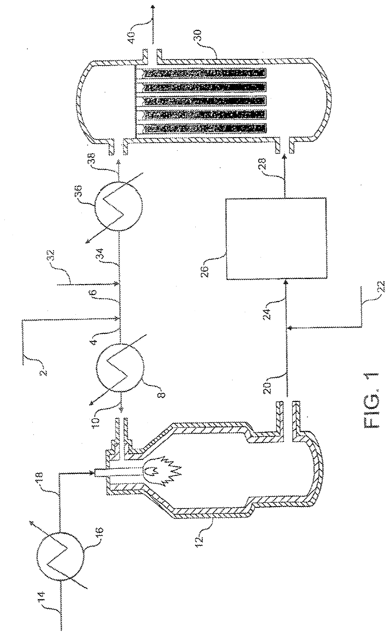
[0097]Referring to FIG. 1, a stream 2 of natural gas is preheated by indirect heat exchange 8, hydrodesulfurized as required, and divided into a first portion 4 and a second portion 6. The first portion 4 is introduced into a POX reactor 12. A stream 14 of oxygen is pre-heated by indirect heat exchange 16 and the pre-heated oxygen stream 18 is also fed to the POX reactor 12. The natural gas and the oxygen are reacted together in the POX reactor 12 to produce first syngas product. A stream 20 of first syngas product is removed from the POX reactor 12 at a temperature of from 1200 to 1400.degree. C.

[0098]A stream 22 comprising carbon dioxide is introduced to and cools the first syngas product stream 20. The cooled stream 24 is fed to a reverse water gas shift reactor 26 in which at least a portion of the carbon dioxide from the cooled stream 24 is reacted with at least a portion of the hydrogen from the cooled stream 24 to produce carbon monoxide and water. The catalytic reaction is e...


PUM


Abstract

Reactive diluent fluid (22) is introduced into a stream of synthesis gas (or “syngas”) produced in a heat-generating unit such as a partial oxidation (“POX”) reactor (12) to cool the syngas and form a mixture of cooled syngas and reactive diluent fluid. Carbon dioxide and/or carbon components and/or hydrogen in the mixture of cooled syngas and reactive diluent fluid is reacted (26) with at least a portion of the reactive diluent fluid in the mixture to produce carbon monoxide-enriched and/or solid carbon depleted syngas which is fed into a secondary reformer unit (30) such as an enhanced heat transfer reformer in a heat exchange reformer process. An advantage of the invention is that problems with the mechanical integrity of the secondary unit arising from the high temperature of the syngas from the heat-generating unit are avoided.

Description

CROSS-REFERENCE TO RELATED APPLICATIONS[0001]This application is a divisional of U.S. patent application Ser. No. 14 / 691,395 filed on Apr. 20, 2015, which is a continuation application of U.S. patent application Ser. No. 13 / 774,833, filed on Feb. 22, 2013, which is a continuation of U.S. patent application Ser. No. 12 / 704,311, filed on Feb. 11, 2010, which is a continuation of U.S. application Ser. No. 10 / 518,038 (now U.S. Pat. No. 7,670,586), filed on Dec. 13, 2005, which is a national stage application of International Application PCT / IB03 / 00695, filed on Feb. 24, 2003, which is a continuation of and claims priority to U.S. application Ser. No. 10 / 083,778, filed on Feb. 25, 2002, the entire disclosures of which are incorporated herein by reference.BACKGROUND[0002]The present invention relates to a process and apparatus for the production of synthesis gas, particularly for but not necessarily limited to, use in the production of hydrocarbon liquid fuels (e.g. using the Fischer-Trop...

Claims


Application Information

Patent Timeline
IPC IPC(8): B01J19/24B01J19/00C01B3/48C01B3/58C10J3/48
CPCC10J3/48C10J2300/1609C01B3/586C01B2203/0844B01J19/0013B01J19/242C01B2203/0445C01B2203/0261C01B3/48C01B2203/0255C01B2203/0283C10J2300/1618C01B2203/0475C01B2203/0244C10J2300/1606B01J2219/00117B01J8/062B01J19/002B01J2208/00504B01J2219/00123B01J2219/00159C01B3/382C01B2203/0233C01B2203/062C01B2203/142C10J2300/0959C10J2300/0989C10K1/024C10K3/04B01J8/067
Inventor WANG, SHOOU-IREPASKY, JOHN MICHAELNATARAJ, SHANKARPENG, XIANG-DONG
Owner NIQUAN ENERGY LLC
Why Eureka
Try Eureka