
Machine Learning to Accelerate Alloy Design

a technology of alloy design and machine learning, applied in machine learning, 3d object support structures, computer peripheral equipment, etc., can solve the problems of inability to predict the experimental definition of multi-component phase diagrams is impractical, and the inability of existing toolsets for icme to predict the effect of am on the material properties of additively manufactured parts

Pending Publication Date: 2020-08-13
IMAGARS
View PDF0 Cites 44 Cited by
  • Summary
  • Abstract
  • Description
  • Claims
  • Application Information

AI Technical Summary

Benefits of technology

The invention is about using a type of neural network (ANN) to predict properties such as fatigue life of metallic components fabricated by additive manufacturing (AM). The invention takes into account the complex process underlying AM and uses custom kernel functions to extract the most out of the limited input data available. Combining machine learning (ML) with physics-based modeling approaches such as thermo-dynamics, first principle effects, empirical rules, mesoscale models, models for dislocation dynamics and slip bands helps to accurately predict the stress / life curves of such components. The invention provides a comprehensive toolset for predicting fatigue properties with superior accuracy than existing tools.

Problems solved by technology

Most binary and some ternary phase diagrams have been measured experimentally, but multi-component systems remain mostly unexplored.
The experimental definition of multi-component phase diagrams is impractical, due to the tremendous amount of work involved.
Existing toolsets for ICME cannot predict how AM affects material properties of additively manufactured parts.
The authors present a problem involving the design of the magnetoelastic Fe—Ga alloy microstructure for the enhanced elastic, plastic, and magnetostrictive properties.
While theoretical models for computing properties given the microstructure are known for this alloy, the inversion of these relationships, to obtain microstructures that lead to desired properties, is challenging, primarily due to the high dimensionality of the microstructure space, due to multi-objective design requirements, and non-uniqueness of solutions.
These challenges render traditional search-based optimization methods incompetent in terms of both searching for efficiency and result optimality.
Experiments with five design problems that involve the identification of microstructures that satisfy both linear and nonlinear property constraints show that the proposed framework outperforms traditional optimization methods with the average running time reduced by as much as 80%. and with the optimality that would not be achieved otherwise.
Despite the high potential of additive manufacturing, it has been found that the fatigue life of as-deposited AM components is often low, compared to wrought components produced by the conventional technology.
As a result, the fatigue performance in AM parts has been attributed to a complex combination of material and process-induced imperfections.
The approach certainly does not address the application of AI or ML to better distribute, monitor and control the processing energy in a laser metal powder bed fusion AM systems, for purpose of real-time process monitoring and control aimed at producing high-quality, defect-free AM parts with build periods comparable or shorter than present ones.
Existing software tools for fatigue prediction cannot consider how additive manufacturing affects the material properties of additively manufactured parts.

Method used


Image

  • Machine Learning to Accelerate Alloy Design
  • Machine Learning to Accelerate Alloy Design
  • Machine Learning to Accelerate Alloy Design

Examples


example 1

6. Prediction of Fatigue Endurance Limit

[0360]The overall methodology for predicting the fatigue resistance is presented in FIG. 22. This is a two-stage prediction process, where we first determine the tensile strength, given an input combination, and then determine the fatigue resistance, given the tensile strength and the inputs.

[0361]FIG. 26 compares the high-cycle fatigue properties of HEAs to those of conventional alloys. The HEAs seem to generally result in higher UTS and endurance limits, compared to conventional alloys. Still, there is a lot of scatter in the data. But despite the scatter, the endurance limit seems primarily correlated with the UTS. Hence, by identifying compositions with larger UTS, one can expect greater fatigue resistance. A key to accurate prediction entails understanding, and properly accounting for (explaining), the sources of variations in the data.

[0362]The scatter in the data is caused by input sources, such as defect levels, process parameters, or...

example 3

8. Prediction of Fatigue Life (Stress Life or Strain Life) and Crack Growth

8.1 Prediction of Fatigue Life Remaining (S / N Curve), in Presence of No Cracks

1. Objective

[0412]For the triplet

(process,stress applied,cycles to failure),  (34)

the goal is to accurately infer the “process” parameter from the combination

(stress applied,cycles to failure),  (35)

in order to properly differentiate between “process” categories.

[0413]Similarly, we can look to estimate “cycles to failure” (fatigue life) from the combination (process, stress applied), or “stress applied” (fatigue strength) from the combination (process, cycles to failure).

2. Method

[0414]The method, presented in FIG. 36, is analogous to the method used for prediction of the endurance limit (see Eq. (16)-Eq. (19)). The main difference is that here we are taking the stress applied as an additional input parameter. The method will be essentially the same as for predicting the endurance limit, except here we are doing separate prediction...

example 4

9 Towards Corrosion Resistant Coatings—Analysis of CMAS and Calcium Sulfate Attacks

9.1 Overall Picture

[0422]This invention can utilize literature materials data or experimental data to develop models or algorithms for machine learning (ML) that will detect data patterns and characteristic trends, learn from the accumulated data, and evolve distinguishing characteristics between calcium-magnesium-alumino-silicate attack (CMAS) and calcium sulfate (CaSO4) hot corrosion, with and without the influence of sea salt, in order to develop resistant coatings to CMAS and calcium sulfate hot corrosion. FIG. 33 presents corrosion data analytics in context with the overall effort to identify high-risk areas for deposit build-up in gas turbines.

[0423]We seek to link structure and chemistry to observed reaction mechanisms to accelerate materials design for corrosive environments.

[0424]The intent is to develop sophisticated physics-based prediction models from experimental data.

[0425]The depositio...


PUM

PropertyMeasurementUnit
temperaturesaaaaaaaaaa
compositionaaaaaaaaaa

Abstract

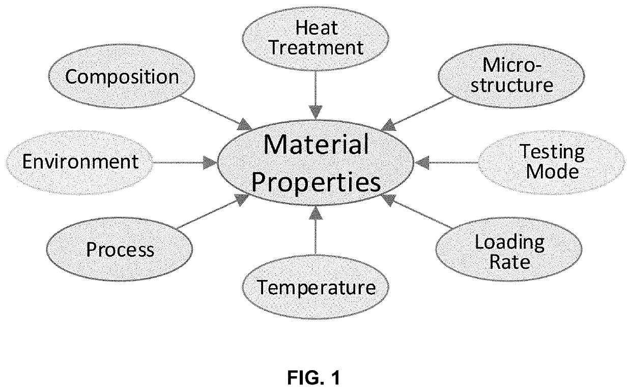
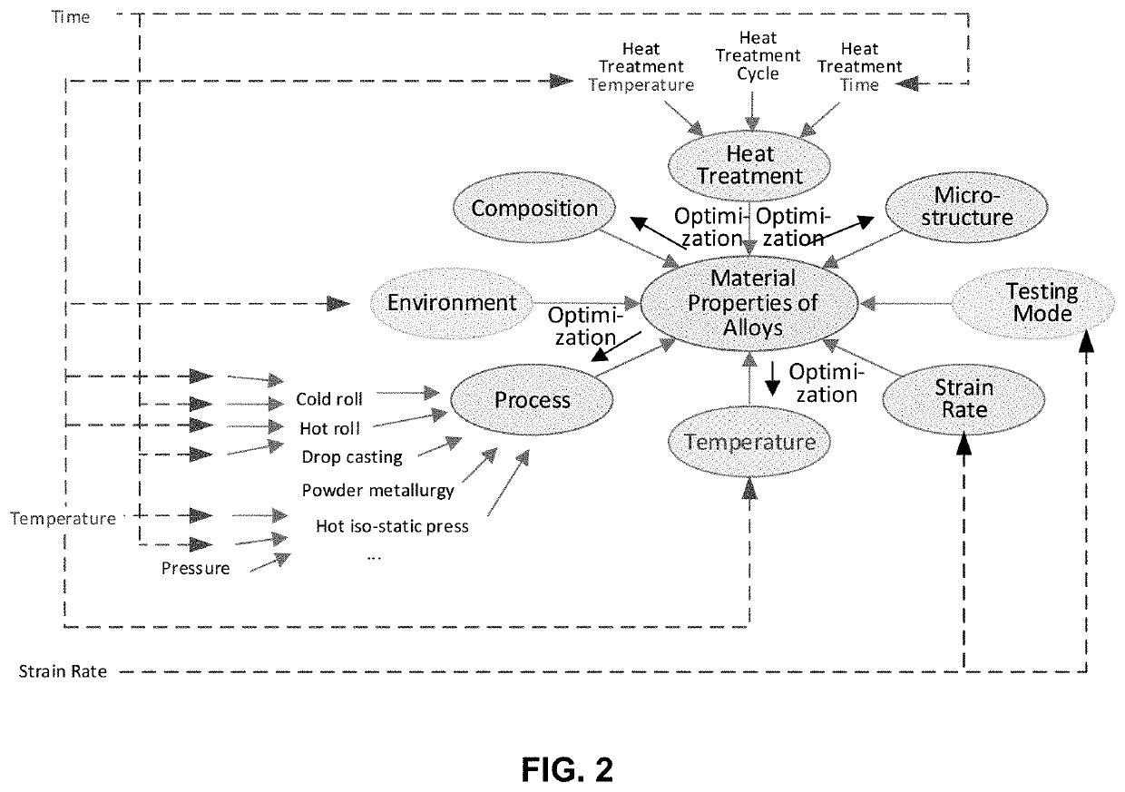
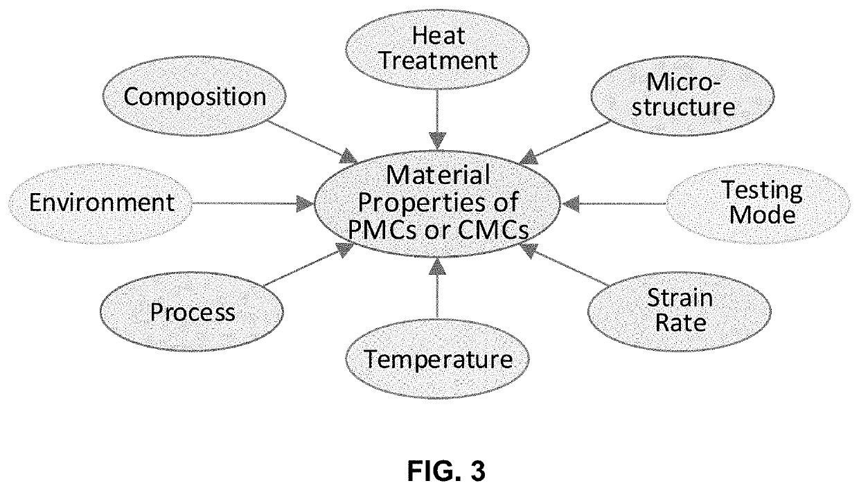
This invention presents an innovative framework for the application of machine learning for identification of alloys or composites with desired properties of interest. For each output property of interest, we identify the corresponding driving (input) factors. These input factors may include the material composition, heat treatment, process, microstructure, temperature, strain rate, environment or testing mode. Our framework assumes selection of optimization technique suitable for the application at hand and data available, starting with simple linear, or quadratic, regression analysis. We present a physics-based model for predicting the ultimate tensile strength, a model that accounts for physical dependencies, and factors in the underlying physics as a priori information. In case an artificial neural network is deemed suitable, we suggest employing custom kernel functions consistent with the underlying physics, for the purpose of attaining tighter coupling, better prediction, and extracting the most out of the—usually limited—input data available.

Description

CROSS REFERENCE TO RELATED APPLICATIONS[0001]This application claims priority under 35 U.S.C. 119(e) to U.S. Patent Application Ser. No. 62 / 801,280, filed on Feb. 5, 2019, the entire contents of which are hereby incorporated by reference.ACKNOWLEDGEMENT OF FEDERAL FUNDING[0002]This utility patent traces its origin to research conducted under support of National Science Foundation Awards 1,447,395 and 1,632,408.[0003]Xuesong Fan and Dr. Peter K. Liaw very much appreciate the support of the U.S. Army Research Office Project (W911NF-13-1-0438 and W911NF-19-2-0049) with the program managers, Drs. M. P. Bakas, S. N. Mathaudhu, and D. M. Stepp.[0004]Dr. Peter K. Liaw thanks the support from the National Science Foundation (DMR-1611180 and 1809640) with the program directors, Drs. G. Shiflet and D. Farkas.BACKGROUND OF THE INVENTION[0005]This patent addresses the application of data analytics and optimization techniques, such as machine learning, to accelerate the design of alloys, exhibit...

Claims


Application Information

Patent Timeline
Patent Type & Authority Applications(United States)
IPC IPC(8): G06K9/62G06N7/00G06N20/00G06F30/27B22F3/105B29C64/393B29C64/153B29C64/268
CPCB29C64/153B29C64/393G06F2113/10G06N7/005B29C64/268B22F3/1055B33Y50/02G06F2119/08G06K9/6202G06N20/00B33Y70/10B22F2003/1057B33Y10/00G06K9/6228G06K9/6232B33Y30/00G06F30/27C22C14/00C22C16/00C22C21/00C22C27/02B33Y70/00C22C19/05C22C30/00C22C27/025C22C27/04C22C27/06B22F10/28B22F12/45B22F10/25B22F10/80B22F10/85B22F12/90B22F10/368B22F10/366B22F5/04G06N3/02G06N20/10Y02P10/25G16C60/00G16C20/70G16C20/30B22F10/22B22F10/36G06N7/01G06F18/213G06F18/211
Inventor STEINGRIMSSON, BALDUR ANDREWLIAW, PETER K.FAN, XUESONGKULKAMI, ANAND A.
Owner IMAGARS
Learn More