Enhanced sample imaging using structured illumination microscopy

a sample imaging and structured illumination technology, applied in the direction of optical radiation measurement, fluorescence/phosphorescence, instruments, etc., to achieve the effect of increasing the signal/noise ratio, improving spatial resolution, and increasing the light throughput of the sampl

Active Publication Date: 2020-10-08
THERMO ELECTRONICS SCI INSTR LLC
View PDF0 Cites 3 Cited by
  • Summary
  • Abstract
  • Description
  • Claims
  • Application Information

AI Technical Summary

Benefits of technology

[0007]Aspects of the invention are associated with methods and apparatuses whereby structured illumination microscopy (SIM) is applied to a scanning microscope, such as a confocal laser scanning microscope or confocal sample scanning microscope, in order to improve spatial resolution. Particular aspects relate to the discovery of important advances in the ability to (i) increase light throughput to the sample, thereby increasing the signal / noise ratio and / or decreasing exposure time, as well as (ii) decrease the number of raw images to be processed, thereby decreasing image acquisition time. Both effects give rise to significant improvements in overall performance, to the benefit of users of scanning microscopes.

Problems solved by technology

However, this applies only to the situation in which a linearly polarized beam fills the entire back aperture of a microscope objective.
Because confocal microscopes do not illuminate an entire sample at once, as in the case of a wide-field microscope, existing SIM systems and their reconstruction algorithms are not directly “drop-in” compatible with confocal microscopes.

Method used


Image

  • Enhanced sample imaging using structured illumination microscopy
  • Enhanced sample imaging using structured illumination microscopy
  • Enhanced sample imaging using structured illumination microscopy

Examples


example 1

Simulation Studies

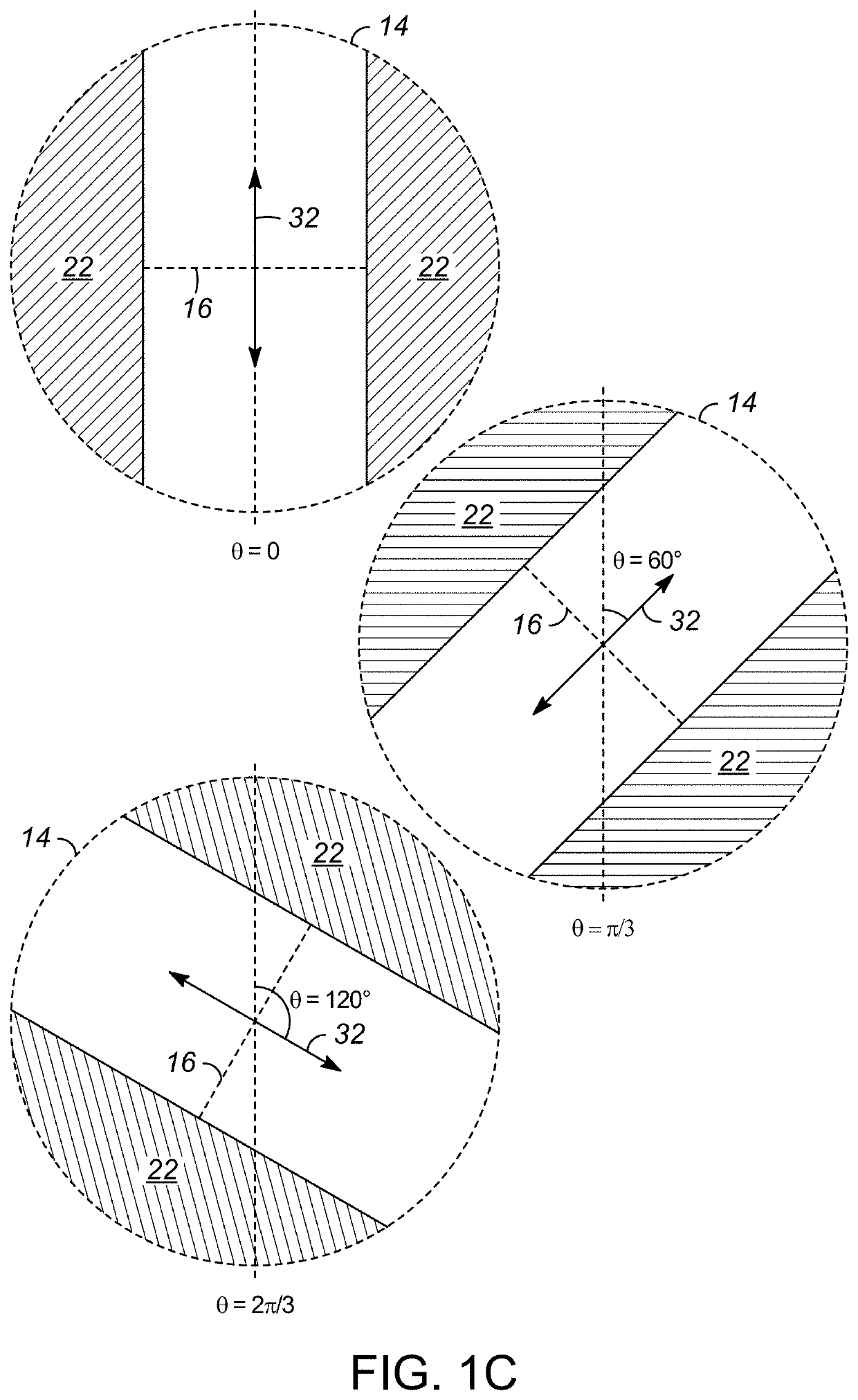
[0046]The imaging of a true sample, having a “ground truth image” was simulated according to the improved imaging methods described herein with confocal-SIM, and compared to conventional CLSM. The simulation results were obtained using an optical propagation library, available as online as “PROPER”. This set of routines, for simulating the propagation of light through an optical system using Fourier transform algorithms (Fresnel, angular spectrum methods), has been thoroughly validated as a physical optical propagation tool, and is commonly used by astronomers in modeling the performance of telescopes. This library was used to simulate, in particular, the confocal and the confocal-SIM point spread functions for a 532 nm laser through a 100×, 0.7 NA objective, focused through a 75 mm focal length lens into a 25 μm confocal pinhole. FIG. 3 illustrates the simulated point spread functions of this confocal SIM example, for three different angles (0, π / 3, 2π / 3) of the l...

example 2

Experimental Demonstration

[0048]A prototype microscope for performing confocal SIM was constructed according to the configuration illustrated in FIG. 2. The dichroic mirror provided the ability to observe the laser spot on the sample, using the microscope camera. This camera was used to acquire images of the spot generated with the SIM patterns from the SLM, in order to prove that same focused fringe patterns were generated, as in the physical optical propagation simulation studies described in Example 1. This was based on a side-by side comparison with the simulation results, in consideration of the circular boundaries around the images obtained in this experimental demonstration, to help indicate approximately the alignment with the confocal pinhole. In the simulation studies, the simulated SIM laser patterns already accounted for the application of the confocal mask, which was the reason for the circular outside shapes of these patterns, as shown in FIG. 3.

[0049]Using a Pelcotec™...


PUM

PropertyMeasurementUnit
focal lengthaaaaaaaaaa

Abstract

Methods and apparatuses are disclosed whereby structured illumination microscopy (SIM) is applied to a scanning microscope, such as a confocal laser scanning microscope or sample scanning microscope, in order to improve spatial resolution. Particular aspects of the disclosure relate to the discovery of important advances in the ability to (i) increase light throughput to the sample, thereby increasing the signal/noise ratio and/or decreasing exposure time, as well as (ii) decrease the number of raw images to be processed, thereby decreasing image acquisition time. Both effects give rise to significant improvements in overall performance, to the benefit of users of scanning microscopy.

Description

CROSS-REFERENCE TO RELATED APPLICATIONS[0001]The present application claims the priority benefit from U.S. Patent Application Ser. No. 62 / 827,921, filed Apr. 2, 2019, which is hereby incorporated by reference herein in its entirety for all purposes.FIELD OF THE INVENTION[0002]The present invention relates to the imaging of samples using a scanning microscope (e.g., a confocal laser scanning or sample scanning microscope) and structural illumination for resolution improvement.BACKGROUND OF THE INVENTION[0003]Conventional light microscopes have a spatial resolution that is limited by diffraction. When the back aperture of a microscope objective is fully filled with collimated light, the image in the focal or sample plane is an Airy disk having a radius rairy (in nanometers, nm) according to:rairy=1.22*λ2*NA,[0004]in which λ (in nm) is the illuminating wavelength and NA (dimensionless) is the numerical aperture of the microscope objective and provides a measure of its resolving power. ...

Claims


Application Information

Patent Timeline
Patent Type & Authority Applications(United States)
IPC IPC(8): G02B21/00G02B21/36G01N21/64G01N21/65G01J3/44
CPCG02B21/0056G02B21/0076G02B21/0072G02B21/008G01J3/4412G02B21/367G02B21/0032G02B21/006G01N21/658G01N21/6458G01N21/65G01N2201/0675G01J1/0437G01J1/4257G01J3/0229G01J3/10G01J3/06G01J3/0218G01J3/2823G01J3/44G01J1/0425
Inventor GEORGIADIS, MICHAEL S.DECK, FRANCIS J.
Owner THERMO ELECTRONICS SCI INSTR LLC
Why Eureka
Try Eureka