

Apparatus and method of catalysis
a technology of electrochemical redox and apparatus, applied in the field of apparatus and method of catalysis, can solve the problems of large driving force, high cost of catalysts, and the detrimental effect of improving one aspect of the catalytic process on the other, and achieve the effect of enhancing redox properties
- Summary
- Abstract
- Description
- Claims
- Application Information
AI Technical Summary
Benefits of technology
Problems solved by technology
Method used
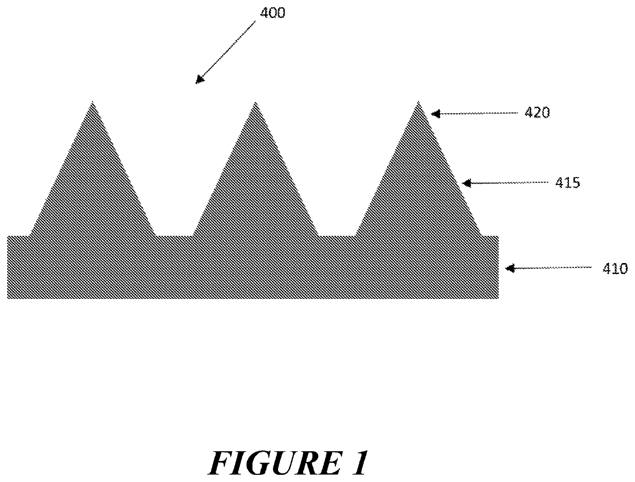
Image

Examples
example 1
SAM Removal at the Tip
[0418]Aim: To demonstrate that charge density (voltage or current) distribution of an electrode array with surface structures can be used to selectively remove the self-assembled monolayer from the apex of surface structures.
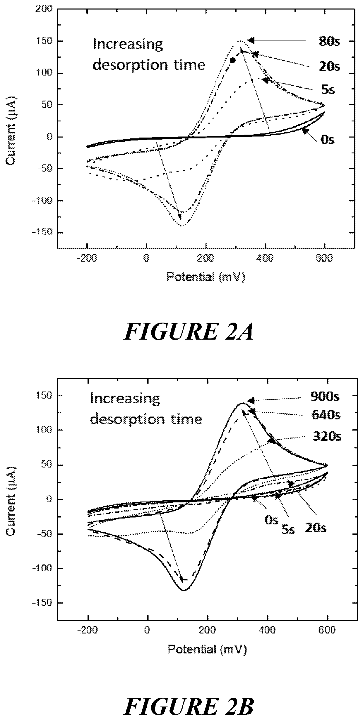
[0419]Method: SAM coated electrodes were immersed in PBS solution. Desorption was carried out by chronoamperometry by applying a reductive potential (−1.1 v for cumulative duration of 0 s, 2.5 s, 5 s, 10 s, 20 s, 40 s, 80 s, 160 s, 320 s, 640 s, and 900 s), and the desorption rate was monitored using cyclic voltammetry in K3FeCN6 at 20 mV / s.
[0420]Results: The gold coated surface structures on the electrode arrays demonstrated a faster desorption profile with a maximum oxidation peak occurring after approximately 10 seconds (FIG. 2a) relative to the flat electrode (FIG. 2b) with a maximum oxidative peak being seen after approximately 20-30 minutes
[0421]Conclusion: Differential charge density (voltage or current) distribution of a three-dimen...
example 1b
SU8 Passivating Layer
[0422]Aim: To demonstrate that charge density (voltage or current) distribution of an electrode array can be increased by the application of a photoresist coating in the valley between the tips
[0423]Method: Gold coated electrodes had SU8 spun coated onto the surface at between 2000-5000 rpm, and cross-linked by exposure to UV. This is to give the thickness of passivating layer in the range of 10 μm to 30 μm.
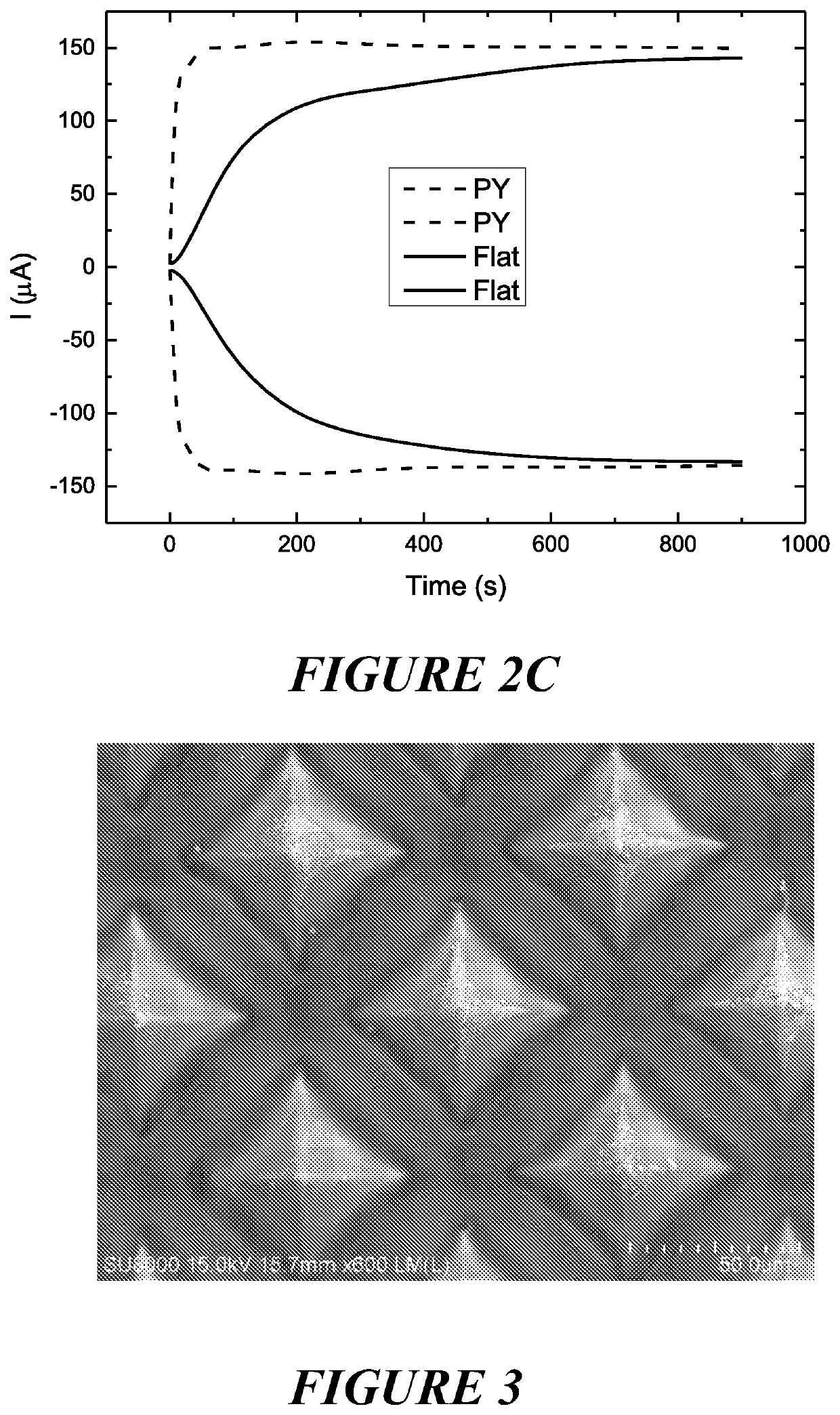
[0424]Results: Platinum was electrochemically reduced onto the exposed tips formed as a series of nano-particles as a result of current focusing (see FIG. 3).
[0425]Conclusion: Differential charge density (voltage or current) was accentuated by the passivating layer and induced formation of nano-particles instead of a film which can lead to enhanced catalytic activity.
example 2
Pt Functionalization at the Tip
[0426]Aim: To demonstrate differential charge density (voltage or current) distribution of an electrode array with surface structures can be used to selectively deposit metals at the apex of the structures.
[0427]Method: Surface structures with a gold electrocatalyst layer were cleaned using reactive ion etching (RIE) with O2 plasma (2 min) and immersed into a Platinum (IV) chloride (1 mM) solution in PBS. The growth of Pt meso-particles was carried out using a square wave potential as follow; a reductive potential (−500 mV) was applied to reduce Pt(II) to Pt (0) on the surface for 15 s, followed an oxidative potential (300 mV) to stop the process. This cycle was continued until the desired amount of deposited Pt was obtained.
[0428]Results: The Pt deposition occurred predominantly at or about the apex of the surface structures as shown in FIGS. 4a and 4b (without passivating) and FIG. 3 (with SU8 passivating layer).
[0429]Conclusion: Due to the higher ch...
PUM
| Property | Measurement | Unit |
|---|---|---|
| width | aaaaa | aaaaa |
| width | aaaaa | aaaaa |
| distance | aaaaa | aaaaa |
Abstract
Description
Claims
Application Information