Eureka AIR delivers breakthrough ideas for toughest innovation challenges, trusted by R&D personnel around the world.

Control scheme for surface steerable drilling system

Inactive Publication Date: 2021-01-21
PETEX ENERGY INC
View PDF0 Cites 2 Cited by
  • Summary
  • Abstract
  • Description
  • Claims
  • Application Information

AI Technical Summary

Benefits of technology

This patent describes a surface steering system that improves drilling efficiency and safety by taking control of the top drive, a drilling device that is commonly used in oil drilling. The system includes a control scheme that is installed in an operator station and uses pre-configured parameters and the operator's instructions to optimize the top drive's control logic and improve drilling efficiency and safety. The system automatically controls the top drive, reducing the workload of the field operator and allowing for more efficient and continuous control. Consequently, the patent proposes a new generation of dedicated drilling device that is safer, faster, and more efficient.

Problems solved by technology

Directional drilling is a very complicated process.
These common practices do not serve well normally.
In the end, the efficiency of drilling is detrimentally affected, and the drilling depth of horizontal wells is limited.
However, these methods still utilize manual control of the top drive, which is inefficient and time consuming.
Due to too many input parameters, strong coupling between parameters, and high nonlinearity, the traditional linearization approximation method cannot be applied to the control system.
However, any such control strategy based on such a simplified model is difficult to adapt to the highly-variable and ever-changing drilling process, resulting in the general low drilling efficiency, and even the situation that the drilling task cannot be completed.
This small zone of rotation will limit the static friction resistance reduction.
The weight may only cause the drilling tool to buckle, randomly form a new friction point, and store the torque in the drill string.
For another disadvantage, the torque stored in the drill pipe will induce a random distribution of the torque accumulation in the drill pipe and a random distribution of the buckling friction points.
This will result in poor controllability and stability of the drill string.
Finally, torque stored in the drill pipe may also cause the accumulation of torque in the drill pipe and cause uncontrollable swinging of the drill pipe.
The ability to increase efficiency and save operational time (and thus saving operational costs) leads to considerable competition in the marketplace.

Method used


Image

  • Control scheme for surface steerable drilling system
  • Control scheme for surface steerable drilling system
  • Control scheme for surface steerable drilling system

Examples


example operation

[0113]A non-limiting example of connection, operation, and use of the control scheme 203 now follows in order to make the above features and advantages of the present disclosure more apparent. The control scheme 203 may include one or more characteristics as set forth and described.

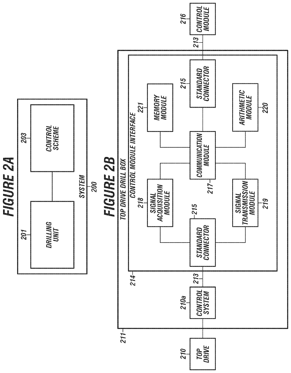
[0114]The control module interface 214 may be a pre-installed module, whereby the interface 214 may be installed in the top drive drill box 211, between the control module 216 and the control system 210a of the top drive 210.

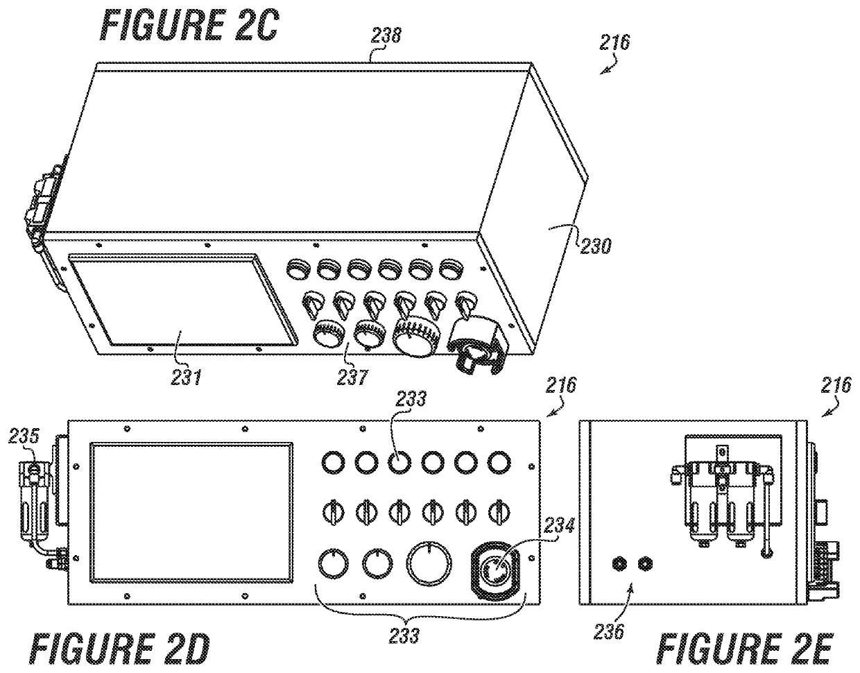
[0115]The control module 216 may be customized according to the actual situation or needs of the top drive (e.g., customized software and hardware) to ensure that the signal communication from and to the control module 216 is stable and correct.

[0116]After completion of coupling the control module interface 214 with the top drive control 210a, all functions and operations of the top drive 210 may remain unchanged whether or not the control module 216 is connected or active.

[0117]The c...


PUM


Abstract

A method for creating and using a control scheme for a drilling operation that includes collecting a set of on-site drilling data for mud motor sliding drilling, wherein the set of on-site drilling data includes information related to at least one of drilling information, rig information, real time data on the drilling operation, and combinations thereof; and division of the set of data from the collecting step into two categories according to a certain proportion. Some of the better-performing data is categorized as an A-class, and the rest as a B-class import system database.

Description

BACKGROUNDField of the Disclosure[0001]This disclosure generally relates to tools used in oil and gas wellbores. More specifically, the disclosure relates to downhole drilling systems that include use of a drill string run into a wellbore and operable to drill a wellbore. In particular embodiments, the drilling system may be for directional drilling, and may include a steerable system controlled from the surface.Background of the Disclosure[0002]A hydrocarbon-based economy continues to be a dominant force in the modern world. As such, locating and producing hydrocarbons continues to demand attention from the oil and gas (O&G) industry. Once hydrocarbons have been found, a well is formed in a surrounding formation so that valuable fluids therein may be produced, and later refined into commercial products, such as gasoline or natural gas.[0003]A well or wellbore is generally drilled in order to recover valuable hydrocarbons and other desirable materials trapped in geological formation...

Claims


Application Information

Patent Timeline
IPC IPC(8): E21B44/00E21B7/04E21B3/02G06N20/00
CPCE21B44/00G06N20/00E21B3/02E21B7/04E21B2200/22G06N3/08G06N20/10G06N5/01
Inventor SUN, GENG
Owner PETEX ENERGY INC
Why Eureka
Eureka Blog
Learn More