
Micro- and nanocontact printing with aminosilanes: patterning surfaces of microfluidic devices for multi- plexed bioassays

a technology of microfluidic devices and aminosilanes, which is applied in the field of micro and nanocontact printing, can solve the problems of high cost, low throughput, and limited control over the geometry and functional properties of the achieved patterns

Inactive Publication Date: 2021-02-18
OKINAWA INST OF SCI & TECH SCHOOL
View PDF0 Cites 0 Cited by
  • Summary
  • Abstract
  • Description
  • Claims
  • Application Information

AI Technical Summary

Benefits of technology

The present invention is a method for creating small patterns on glass using a simple aqueous-based technique called microcontact printing. This method can make patterns with feature sizes ranging from a few hundred microns to 200 nm. Combining this patterning technique with sensing technologies, highly sensitive bioassay systems can be developed in the near future. The invention allows for the creation of stable micro- and nanopatterns on glass substrates, which is useful for the development of microfluidic devices and other applications.

Problems solved by technology

These techniques are either plagued by high costs, low throughput, or limited control over the geometry and functional properties of the achieved patterns.
Particularly, nanopatterning of biomolecules has been laborious and integration of these patterned substrates into microfluidic devices has been a challenge.
Although the proposed method enables the successful generation of multiple protein nanopatterns within a microfluidic channel, the major drawbacks are the requirement of complex fabrication techniques to create the nanopatterned substrates, the repeated fabrication of new surfaces prior to each use, and the non-covalent coupling of proteins onto the nanopatterns inducing potential desorption when subjected to flow.
), they are unable to withstand high shear stresses introduced by the flow present in microfluidic channels.
As a result, it gives rise to gradual desorption and degradation of patterned biomolecules that lead to reduced device performance and poor shelf life.
Secondly, since partial dehydration of biomolecules is a prerequisite to the μCP technique, the probability of protein denaturation and impaired biological activity is high.
Additionally, the lack of control over the orientation of the printed proteins has been lamented and could be responsible for the suboptimal interactions in bioassays due to the inaccessibility of the binding sites.
Lastly, patterning a substrate with multiple biomolecules proves to be difficult and time-consuming, as each individual stamp can only he utilized to pattern a single ink at a time.
However, alignment of the channels with the patterns is difficult to achieve since the proteins are deposited onto the substrates prior to the bonding of the device.
Additionally, as the proteins are dried briefly before alignment, viability for long-term studies is a concern due to their potential degradation.
Although this method provides simplicity and potential for achieving multiplexing in microfluidic devices, the resolution of obtained features is not only limited by the microfluidic channel dimensions, but also by the printing process since existing μCP methods rely on the use of organic solvents that can potentially swell the PDMS substrate and increase the dimensions of the patterned features (J. N. Lee, C. Park and G. M. Whitesides, Analytical Chemistry, 2003, 75, 6544-6554).
Although the degree of PDMS swelling does not significantly affect micron-size features in the stamps, it proves to be a limiting factor while attempting to achieve nanoscale APTES patterns.

Method used


Image

  • Micro- and nanocontact printing with aminosilanes: patterning surfaces of microfluidic devices for multi- plexed bioassays
  • Micro- and nanocontact printing with aminosilanes: patterning surfaces of microfluidic devices for multi- plexed bioassays
  • Micro- and nanocontact printing with aminosilanes: patterning surfaces of microfluidic devices for multi- plexed bioassays

Examples


example 1

APTESaq Micropatterns for Grafting of Biomolecules Within Microfluidic Devices

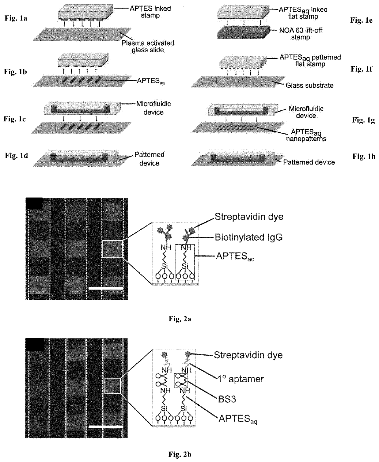
[0078]To facilitate the patterning of biomolecules within microfluidic devices regardless of the molecular charge, a microcontact printing process was developed to print aqueous APTES (APTESaq) in closed microfluidic devices (schematic in FIGS. 1a-1d), to create covalent bonds between the surface and the biomolecules. Here, APTESaq was printed onto a plasma activated glass slide using a PDMS stamp (FIGS. 1a-1b and bonded to a plasma activated PDMS microfluidic device to enclose the vertical print within the horizontal microfluidic channels. The assembled device was heated at 85° C. for 5 minutes to drive the formation of a covalent siloxane bond between the reactive silanols in APTES and the hydroxyl (—OH) groups on the glass substrate (J. A. Howarter and J. P. Youngblood, Langmuir, 2006, 22,11142-11147.). The unpatterned regions within the device were then blocked for 30 min by flowing a solution of 2% PE...

example 2

An Aminosilane Nanopatterns for Grafting of Biomolecules Within Microfluidic Devices

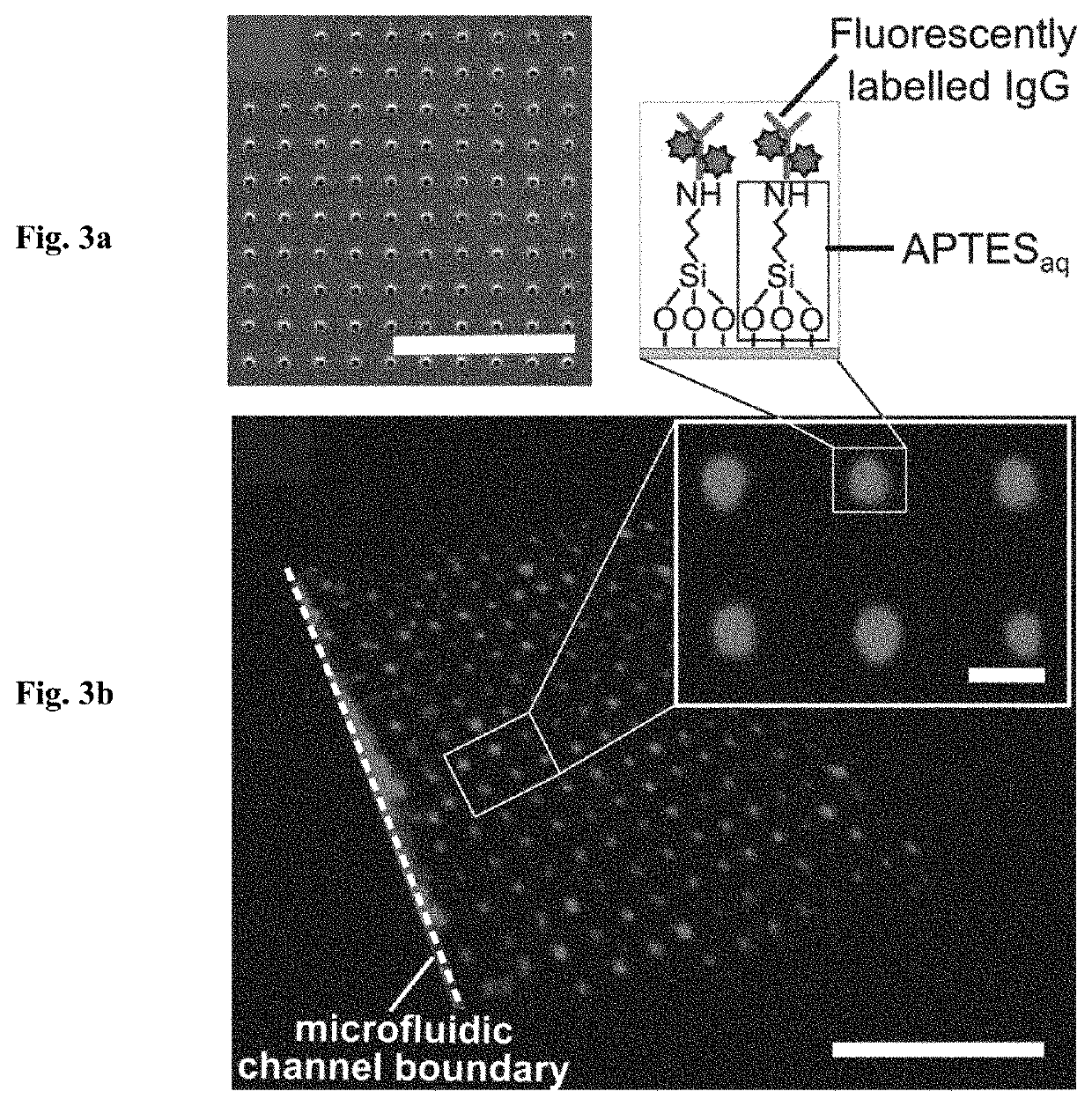
[0082]In addition to successfully creating micropatterns of APTES to covalently pattern biomolecules, we further demonstrate a simple lift-off nanocontact printing method for creating nanopatterns of APTESaq within microfluidic channels to subsequently graft biomolecules covalently. Following a previous protocol (S. G. Ricoult, M. Pia-Roca, R. Safavieh, G. M. Lopez-Ayon, P. Grutter, T. E. Kennedy and D. Juncker, Small, 2013, 9,3308-3313), disposable epoxy lift-off stamps (FIG. 3a) replicating a wafer with nanoholes were obtained through a double replication process via a PDMS intermediate replica.

[0083]A flat PDMS stamp was then inked with the APTESaq solution, rinsed and dried before being pressed against the plasma activated lift-off stamp for 5 s (FIG. 1e). The flat PDMS stamp with the remaining APTESaq nanopattern was then pressed against a plasma activated glass slide for 5 s (FIG. 1f). By utili...

example 3

Aptamer-based Anti antibody-based Immunoassays

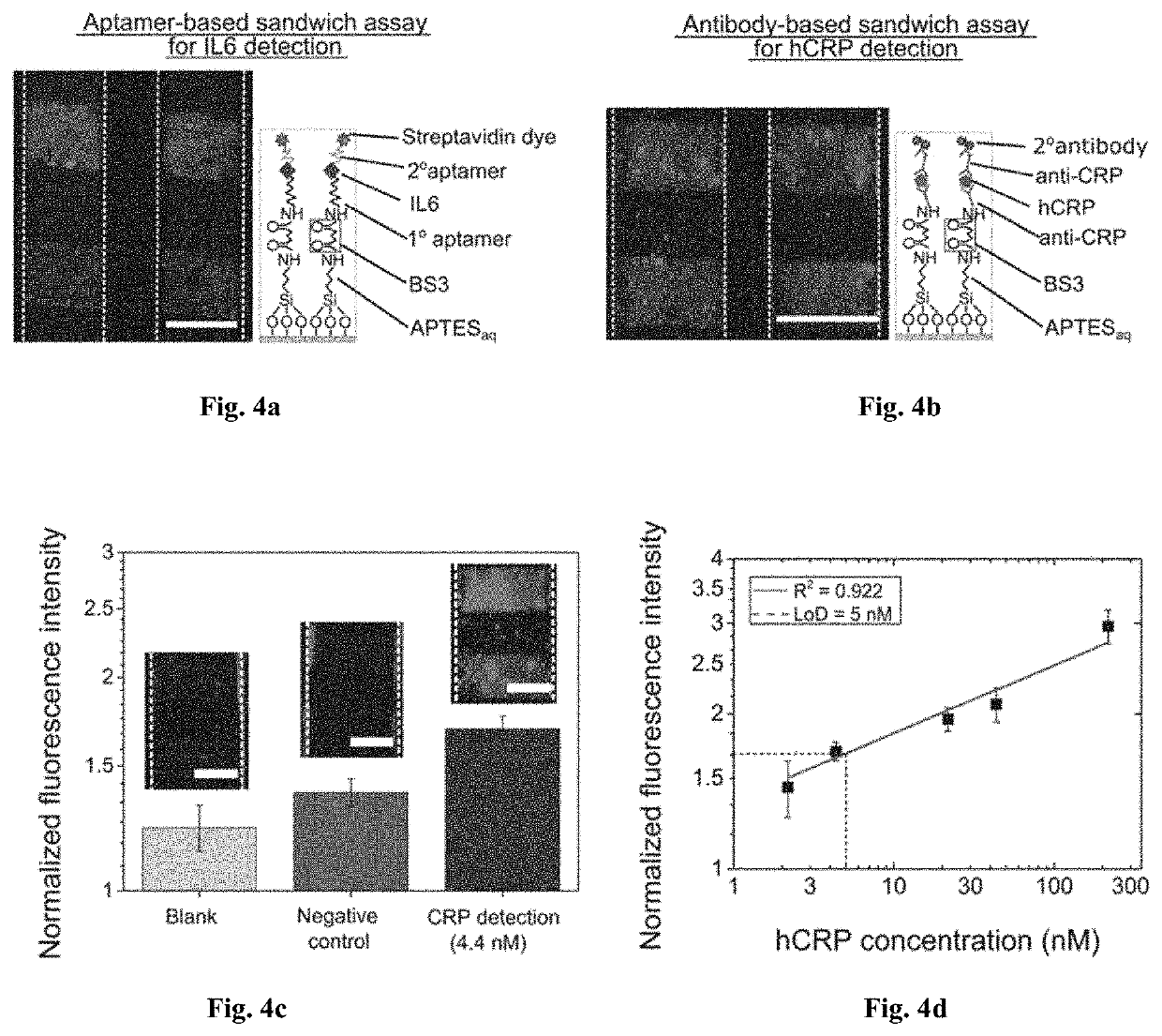
[0085]Interleukin-6 (IL6) (J. S. Yudkin, M. Kumari, S. E. Humphries and V. Mohamed-Ali, Atherosclerosis, 2000. 148, 209-214.; A. G. Vos, N. S. Idris, R. E. Barth, K. Klipstein-Grobusch and D. E. Grobbee, PloS one, 2016, 11, e0147484.) and human C-reactive protein (hCRP) (I. Kushner, Science, 2002, 297, 520-521.; P. M. Ridker, Circulation, 2003, 107, 363-369.) are the most important biomarkers of neurological, cardiovascular and other pathophysiological conditions that arise from tissue inflammation or infection. Quantitative detection of these biomarkers has immensely helped in early diagnosis and treatment of these diseases. In order to accurately diagnose these diseases sensitive assays and biosensing technologies are required to reliably detect minute quantities of these biomarkers (S. K. Vashist, A. Venkatesh, E. M. Schneider, C. Beaudoin, P. B. Luppa and J. H. Luong, Biotechnology advances, 2016,34, 272-290.; A. Qureshi, Y. Gurbuz a...


PUM

PropertyMeasurementUnit
diameteraaaaaaaaaa
sizesaaaaaaaaaa
sizesaaaaaaaaaa

Abstract

It is an object of the present invention to achieve rapid surface patterning of biomolecules within microfluidic devices with high reproducibility. In this work, we present a new means of creating micro- and nano-patterns of aminosilanes within microfluidic devices via an aqueous based microcontact printing technique. To minimize the diffusion of molecules into the PDMS stamp, we use water as the inking solvent and enforce short incubation and contact times during the printing process to preserve the pre-defined resolution of patterned features. These patterns then serve as the building block to couple multiple biomolecules in solution onto a single surface for subsequent bioassays.

Description

CROSS-REFERENCE TO RELATED APPLICATIONS[0001]This application is the Divisional of U.S. patent application Ser. No.: 16,073,791, filed on Jul. 29, 2018, which is the National Stage Entry of PCT / JP2017 / 003621, filed Feb. 1, 2017, which claims the benefit of priority of U.S. Provisional Patent Application No. 62 / 290,067, filed Feb. 2, 2016, the contents of which are incorporated in their entireties as portion of the present application by reference herein.TECHNICAL FIELD[0002]The invention is related to the area of micro- and nanocontact printing. In particular, it is related to micro- and nanocontact printing with aminosilanes: patterning surfaces of microfluidic devices for multi-plexed bioassays.BACKGROUND ART[0003]Since the early 1980's, microfluidic systems have advanced significantly to satisfy the growing demand for the miniaturization of bioassay devices with applications ranging from disease diagnostics (W. Su, X. Gao, L. Jiang, and, J. Qin, Journal of Chromatography A, 2015,...

Claims


Application Information

Patent Timeline
Patent Type & Authority Applications(United States)
IPC IPC(8): B01L3/00C12M1/00G01N33/543G01N33/552
CPCB01L3/502707C12M1/00G01N33/54353B01L2300/123G01N33/552B01L2300/0636B01L2300/0896G01N33/54393
Inventor FRIED, AMY SHENRICOULT, SEBASTIEN GEORG GABRIEL
Owner OKINAWA INST OF SCI & TECH SCHOOL
Learn More