Implant and a method of making the implant and a method of calculating porosity of a porous material

a technology of porous material and implant, which is applied in the field of implants and a method of making implants, can solve the problems of limited application, high biocompatibility of titanium, and direct reverse engineering methods, and achieve the effects of accurate measurement of porosity of porous materials, low cost, and relatively inexpensive implants

Active Publication Date: 2021-04-15
B ONE MEDICAL (SUZHOU) CO LTD +2
View PDF10 Cites 1 Cited by
  • Summary
  • Abstract
  • Description
  • Claims
  • Application Information

AI Technical Summary

Benefits of technology

[0009]It is an object of the present invention to provide a relatively low cost porous implant and a method of making the implant relatively inexpensive. Another object of the present invention is to provide a method capable of more accurately measuring the porosity of a porous material.

Problems solved by technology

However, tantalum is very expensive, thus limited its applications.
In contrast, titanium is more cost effective and has been shown to have high biocompatibility.
However, the direct reverse engineering method has two disadvantages.
Another disadvantage of the direct reverse engineering method is the properties of the bone structure captured by this method is location specific and bone specific.
This variation of bone source and site-specific nature of this approach makes the direct reverse engineering method difficult to utilize and apply generally to different implants and can be expensive to characterize all the myriad variables to create a representative structure for use in large scale production of implants.
The extra complexity of the exact anatomic structures adds the need for significantly more computational resources and additionally these structures are harder to pattern into larger forms and blocks because of their anisomery.
Because they do not have symmetric properties, these structures must scan larger regions which are digitally acquired at lower resolution by necessity or they must scan many multitudes of sites at high resolution by dissecting and extracting from small blocks of a larger bone which is costly, time consuming, and does not solve the patterning problem in itself.
There is an additional technical challenge to quantitatively measure strut thickness, pore diameter, and porosity in real implant component.
This is labor intensive and is prone to errors.
On the other hand, ASTM F3259-17, “Standard guide for Micro-computed tomography of tissue engineered scaffold.” has been widely used for polymer and ceramics but is not recommended for use with porous metals because metallic artifacts significantly increase measurement errors.
First, the direct reverse engineering approach did not work well for highly porous reticulated foam.
The extremely high surface area of the foam and large volume geometry of orthopedic implants made the digital file too large to store and operate on using typical workstations and laptop computers.
Another unexpected result was that the strut size, pore diameter, and porosity were not able to be replicated by direct reverse engineering.
The pore structures were limited, the specific human sites of implants were multiple, and the resolution of 3D printing process was limited by laser beam width and other DMLS parameters.
This method is cumbersome and needs a lot of experiments.
Engineers have struggled for decades to accurately measure porous metal structure using micro-CT method, due to metal artifacts.
The metal artifacts artificially overestimate strut thickness, thus these methods typically historically resulted in lower pore diameter and porosity than the actual porosity.

Method used


Image

  • Implant and a method of making the implant and a method of calculating porosity of a porous material
  • Implant and a method of making the implant and a method of calculating porosity of a porous material
  • Implant and a method of making the implant and a method of calculating porosity of a porous material

Examples


example 1

ed Porous Titanium Sample with 1:1 Scale Ratio to SiC Foam

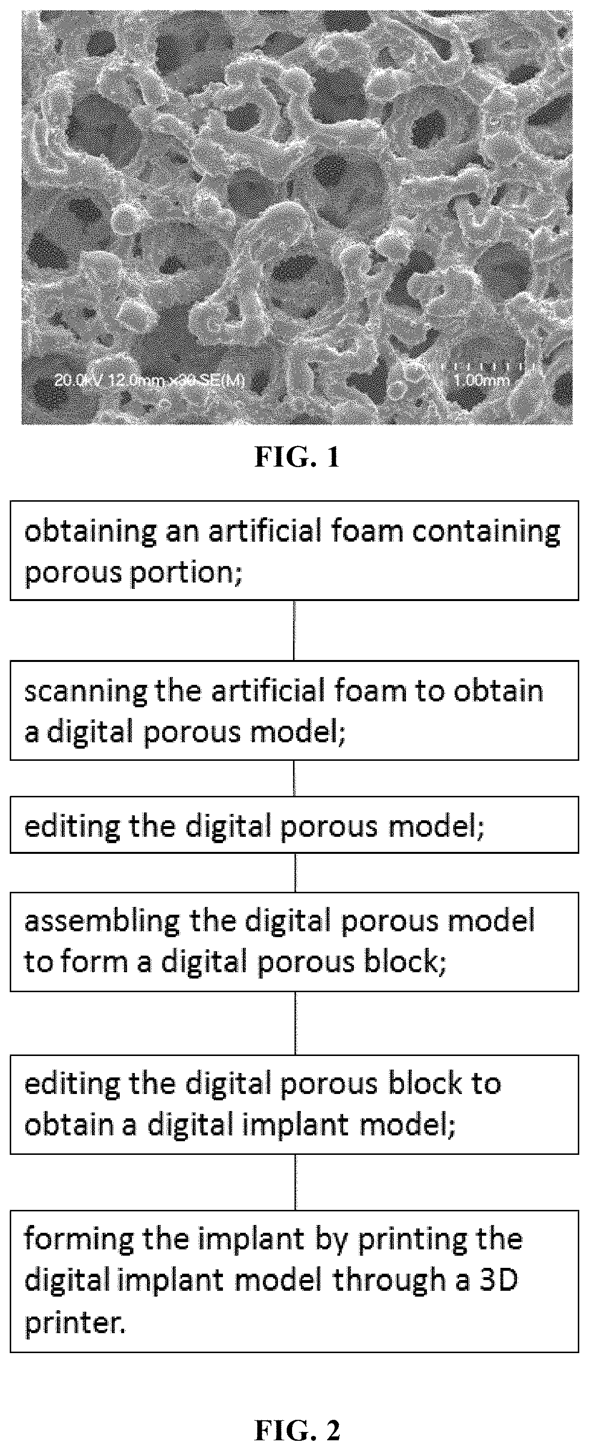
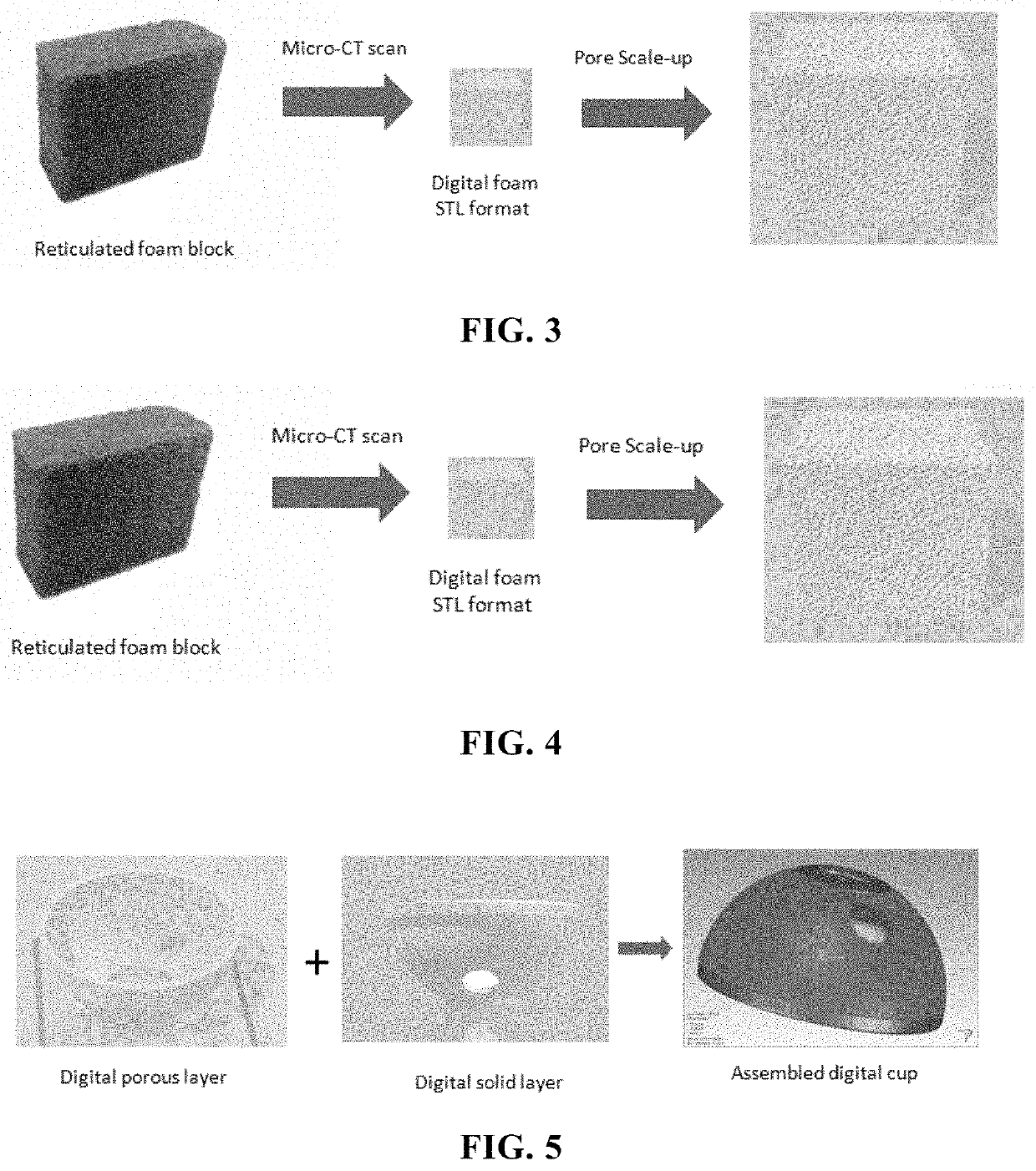
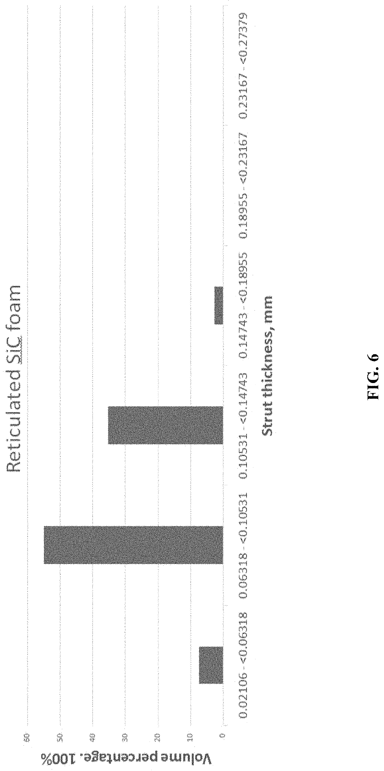
[0094]A reticulated titanium porous foam with 1:1 ratio to 80 PPI SiC foam was made according to process in FIG. 2. The 80 PPI SiC foam was made by Ultramet INC (1217 Montague Street, Pacolma, Calif. 91331, USA). The SiC foam has porosity 80 pores per inch (PPI). A foam block with dimension of 30 mm×20 mm×12.5 mm was scanned by micro-CT at a voxel of 20 microns at Microphonics INC (1550 Pond Road, Suite 110, Allentown, Pa. 18104, USA). The micro-CT scan parameters of SiC foam were Bruker SkyScan 1173 micro-CT, voxel 20 μm, source voltage 100 kV, source current 62 μA. Reconstructions were completed using Bruker NRecon software, porosity analysis was done using Bruker CTAn software and STL models were made using Synopsis Simpleware software. There was no ring artifect correction, smoothing. Beam hardening correction 40%.

[0095]A ½″ cube (12.5 mm×12.5 mm×12.5 mm) was digitally cut out from the original 30 mm×20 mm×12.5 mm block. ...

example 2

ed Porous Titanium Sample with 1.25:1 Scale Ratio to SiC Foam

[0099]All process parameters were the same as Example 1, except the digital STL file of 80 PPI SiC foam was magnified to 1.25 scale in three-dimensional geometry.

example 3

ed Porous Titanium Sample with 1.50:1 Scale Ratio to SiC Foam

[0100]All process parameters were the same as Example 1, except the digital STL file of 80 PPI SiC foam was magnified to 1.5 scale in three-dimensional geometry.


PUM

PropertyMeasurementUnit
volumeaaaaaaaaaa
pore sizeaaaaaaaaaa
pore diameteraaaaaaaaaa

Abstract

A method of making an implant having a porous portion is disclosed. The method comprises the following steps: obtaining an artificial foam containing porous portion; scanning the artificial foam to obtain a digital porous model; editing the digital porous model; assembling the digital porous model to form a digital porous block; editing the digital porous block to obtain a digital implant model; forming the implant by printing the digital implant model through a 3D printer. An implant and a method of calculating porosity a porosity of a porous material are also disclosed.

Description

FIELD OF THE INVENTION[0001]This invention is related to a method of making an implant with reticulated titanium porous layer as well as an implant with reticulated titanium porous layer and substrate portion by three-dimensional (3D) printing process.BACKGROUND OF THE INVENTION[0002]Cementless fixation has been widely used for orthopedic implant for long term survival rate. Ideal integration of bone into and onto porous layer of implants provides interlocking at implant / bone interface by bone ingrowth. Reticulated tantalum foam has similar pore structure as human trabecular bone and has clinically demonstrated good fixation and bone ingrowth results. A pore size of greater than 150 μm facilitates the ingrowth of mineralized bone. A pore diameter of 200 μm corresponds to the average diameter of an osteon in human bone, while a pore diameter of 500 μm corresponds to remodeled cancellous bone. However, tantalum is very expensive, thus limited its applications.[0003]In contrast, titani...

Claims


Application Information

Patent Timeline
Patent Type & Authority Applications(United States)
IPC IPC(8): A61F2/30A61L27/36A61L27/56A61F2/28A61L27/04
CPCA61F2/30942A61L27/3608A61L27/56A61F2/28A61F2002/30948A61F2002/3092A61F2002/30011A61F2310/00023A61F2002/30985A61L27/04A61F2/34A61F2/30767A61F2002/30971A61L27/06B33Y80/00A61F2310/00431A61F2310/00467A61F2310/00461A61F2310/00742A61F2310/00544A61F2310/0088A61F2310/00748A61F2310/00449A61L2420/02A61L27/08B22F10/85B33Y50/02
Inventor ZHANG, ZONGTAOLIEPINS, IMANTSLOWRY, MICHAEL
Owner B ONE MEDICAL (SUZHOU) CO LTD
Why Eureka
Try Eureka