Integrated bi-directional axial gradient refractive index/diffraction grating wavelength division multiplexer

a technology of refractive index and diffraction grating, which is applied in multiplex communication, semiconductor lasers, instruments, etc., can solve the problems of difficult to improve transmission speed and limited optical transmission rate, and achieve high-performance imaging, increased ruggedness, environmental and thermal stability, and increased alignment sensitivity.

Inactive Publication Date: 2000-01-04
AUXORA
View PDF70 Cites 117 Cited by
  • Summary
  • Abstract
  • Description
  • Claims
  • Application Information

AI Technical Summary

Benefits of technology

Further, the device of the present invention is inherently fully bi-directional and can be used simultaneously as a multiplexer and demultiplexer for applications such as network hubs or intersections that distribute channels to various areas of a network. The axial gradient refractive index and diffraction grating-based WDM devices of the present invention are unique because they contain one or more homogeneous index boot lenses which allows integration of all the optical components into a single integrated device. This greatly increases the ruggedness, environmental and thermal stability while simultaneously avoiding the introduction of air spaces which cause increased alignment sensitivity, device packaging complexity, and cost.
Additionally, the homogeneous index boot lenses provide large, planar surfaces for device assembly, alignment and the integration of additional device functions. The use of an axial gradient refractive index lens allows very high performance imaging from a lens with traditional spherical surfaces, thereby providing the diffraction-limited optical imaging necessary for WDM applications. Further, axial gradient refractive index lenses are formed with high quality and low cost. Alternately, aspheric shaped lenses could be used in place of axial gradient refractive index lenses; however, the collimating performance is the same, but it is exceedingly difficult to create a one-piece, inte

Problems solved by technology

Increasing the optical transmission rate is increasing limited by speed and economy of the electronics surrounding the fiber optic system.
This technology has for the past 20 ye

Method used


Image

  • Integrated bi-directional axial gradient refractive index/diffraction grating wavelength division multiplexer
  • Integrated bi-directional axial gradient refractive index/diffraction grating wavelength division multiplexer
  • Integrated bi-directional axial gradient refractive index/diffraction grating wavelength division multiplexer

Examples


first embodiment

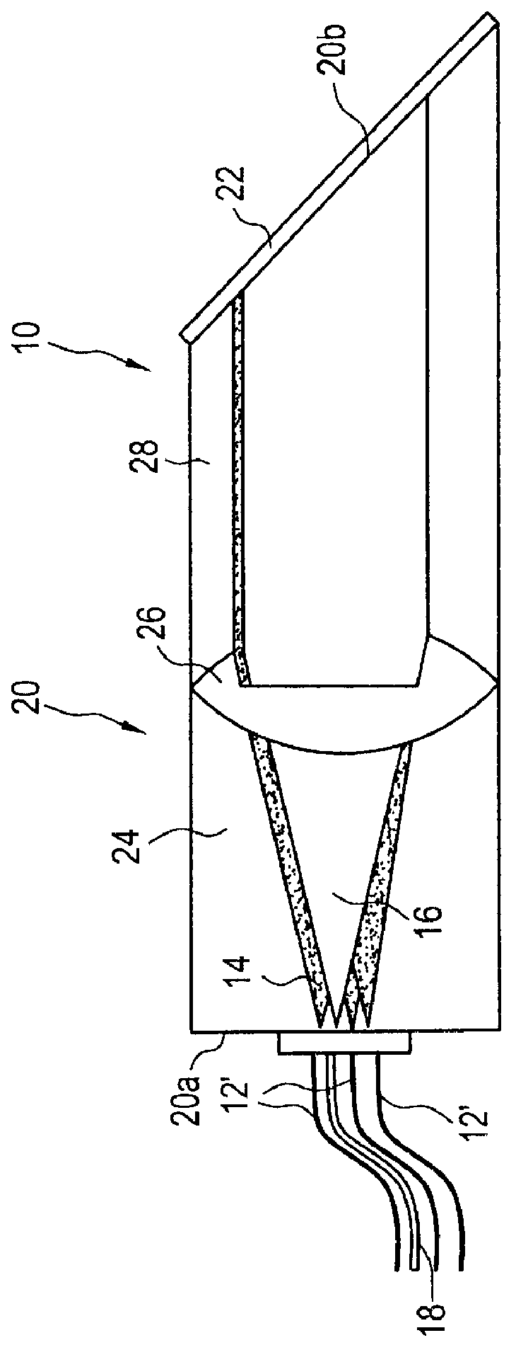
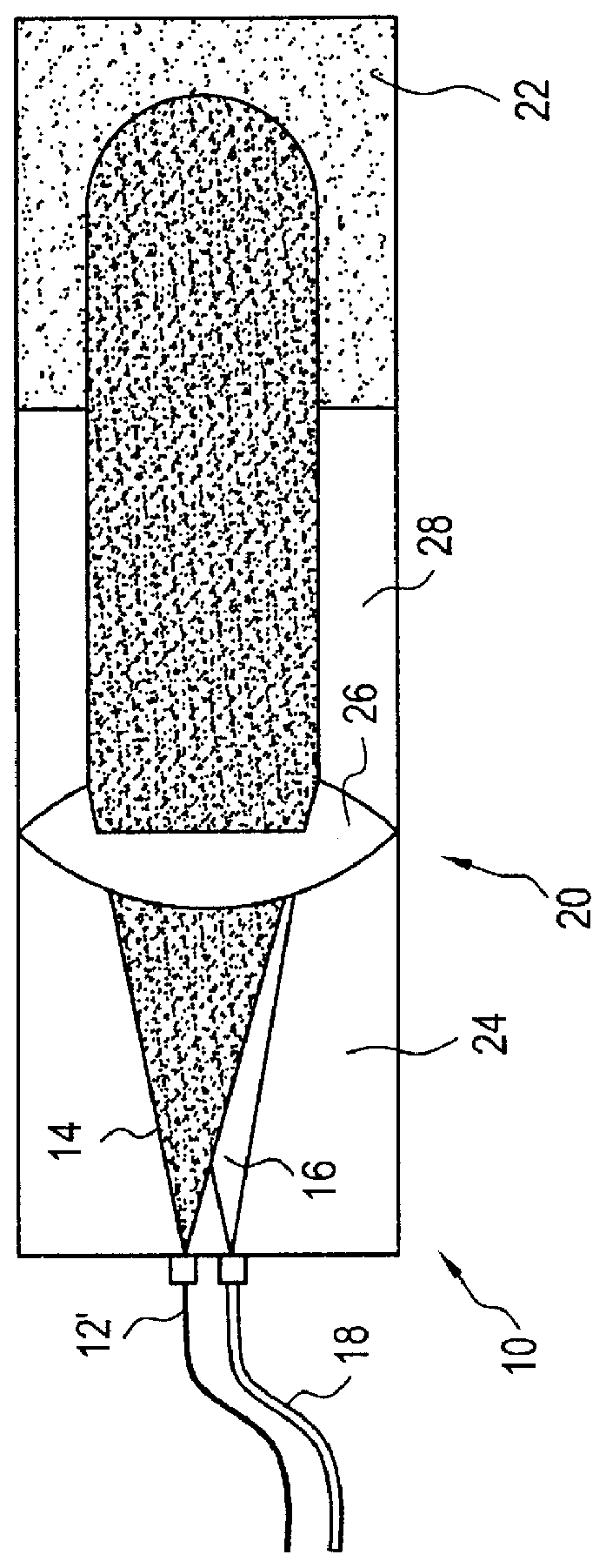
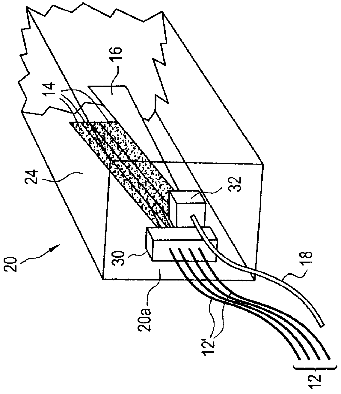
The device 10 of the first embodiment takes an input fiber array 12 of N discrete wavelengths of light 14 and spatially combines them into a single optical beam 16 and outputs the single beam to a single optical fiber output 18. Each wavelength is transmitting information superimposed on it by other means, which are not shown here and which do not form a part of this invention, but are well known in this art.

The device 10 further comprises a coupler element 20; on the exit surface 20b of the coupler element is formed or placed a near-Littrow diffraction grating 22. The near-Littrow diffraction grating 22 provides both the function of angularly dispersing optical beams of differing wavelength and reflecting the optical beams back at very nearly the same angle as the incident angle.

In the present invention, the diffraction grating 22 is used to provide angular dispersion, the amount of which depends upon the wavelength of each incident optical beam. Further, the diffraction grating 22...

second embodiment

In the second embodiment, the device 10 shown in FIG. 1, as with all of the devices described herein, may be operated in the converse configuration, with a single optical fiber input 18 that introduces a single polychromatic light beam 16 carrying multiple discrete wavelength channels. The channels are spatially separated by the demultiplexing function of the device 10 for output to a plurality of optical fibers 12'. Each output fiber 12' carries only a single and discrete wavelength channel. Function ally, in this embodiment, the demultiplexer provides an identical but opposite flnction to the multiplexer device 10 described in FIG. 1. In the demultiplexer embodiment, a plurality of photodetectors 36 shown in FIG. 2c, may be used in place of a plurality of optical fibers 12' to provide optical beam outputs for the wavelength division demultiplexer. The array of photodetectors 36 may either be butt-coupled to the WDM de vice 10, may be longitudinally separated, or may have appropria...

fourth embodiment

In a fourth embodiment, shown in FIG. 4, an array of non-linear electrooptic elements 38 is integrated to provide a capability for selectively routing the multiplexed light 16 into one of several possible colinear fiber outputs 18a, 18b, 18c, 18d, 18e. This is exceedingly valuable for optical networking, whereas the wavelength division multiplexer device 10 can provide simultaneous integrated multiplexing and routing functions. The electrooptic element array 38 is an electrically controlled solidstate optical material in which the refractive index can be modified by varying the electrical current applied to the material. Such electrooptic elements are well-known in the art; examples include lithium niobate, and certain polymer materials.

The output array 18 is separated from the surface 20a by an optional spacer or blank 40. The blank 40 merely provides the same spacing as the beamsteering array 38 to enable ease of input and output coupling.

The change in refractive index is used to ...


PUM


Abstract

A wavelength division multiplexer is provided that integrates an axial gradient refractive index element with a diffraction grating to provide efficient coupling from a plurality of input optical sources (each delivering a single wavelength to the device) which are multiplexed to a single polychromatic beam for output to a single output optical receiver. The device comprises: (a) means for accepting optical input from at least one optical source, the means including a planar surface; (b) a coupler element comprising (1) an axial gradient refractive index collimating lens having a planar entrance surface onto which the optical input is incident and (2) a homogeneous index boot lens affixed to the axial gradient refractive index collimating lens and having a planar but tilted exit surface; (c) a diffraction grating, such as a Littrow diffraction grating, on the tilted surface of the homogeneous index boot lens which combines a plurality of spatially separated wavelengths from the optical light; and (d) means to output at least one multiplexed, polychromatic output beam, the means including a planar surface. The device may be operated in the forward direction as a multiplexer or in the reverse direction as a demultiplexer.

Description

The present invention relates generally to axial gradient refractive index lenses, and, more particularly, to axial gradient refractive index lenses employed in wavelength division multiplexing applications.Wavelength division multiplexing (WDM) is a rapidly emerging technology that enables a very significant increase in the aggregate volume of data that can be transmitted over optical fibers. Traditionally, most optical fibers have been used to unidirectionally carry only a single data channel at one wavelength. The basic concept of WDM is to launch and retrieve multiple data channels in and out, respectively, from an optical fiber. Each data channel is transmitted at a unique wavelength, and the wavelengths are appropriately selected such that the channels do not interfere with each other, and the optical transmission losses of the fiber are low. Today, commercial WDM systems exist that allow transmission of 2 to 32 simultaneous channels.WDM is a cost-effective method of increasin...

Claims


Application Information

Patent Timeline
IPC IPC(8): G02B6/34G02B6/42G02B6/28G02B6/293
CPCG02B6/29307G02B6/2931G02B6/2938G02B6/4246
Inventor DUECK, ROBERT H.WADE, ROBERT K.HUNTER, BOYD V.DEMPEWOLF, JOSEPH R.
Owner AUXORA
Why Eureka
Try Eureka