The increased amount of liquid leads to the use of dilute solutions (typically a 150 mmol amino acid /
liter of solution) to minimize costs, since the amino acids are expensive.
With dilute solutions, it is difficult to obtain high concentrations of amino acids and hence fast chemical reactions between the amino acids and the growing chain.
Further, when the resin is washed and filtered (in a flask) via batch
dilution, it is virtually impossible, in a limited number of batch washes, to remove from the resin all the DCM and TFA used.
As a result, the
contact time of the peptide chain with the DCM and TFA cannot be accurately controlled.
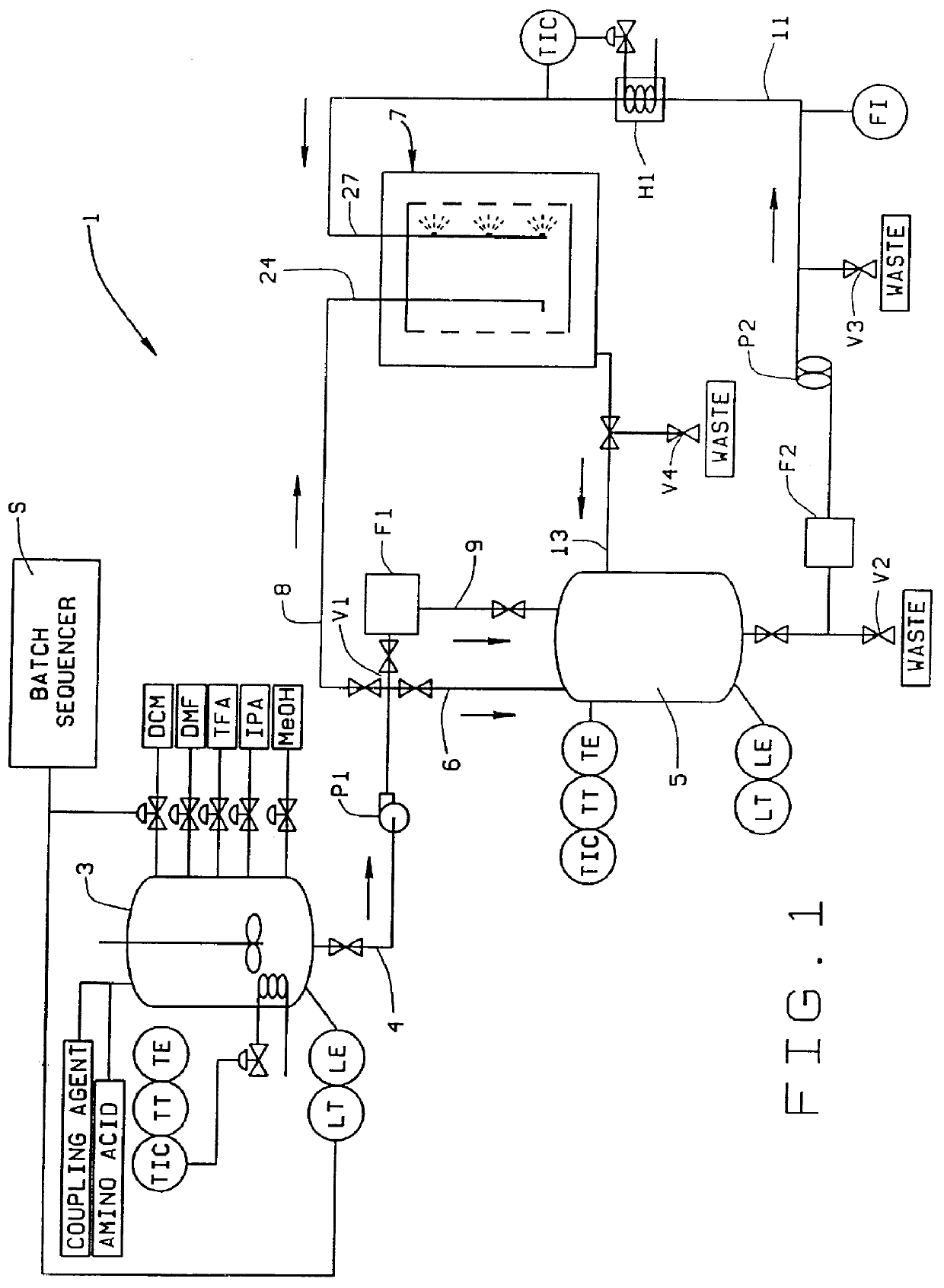
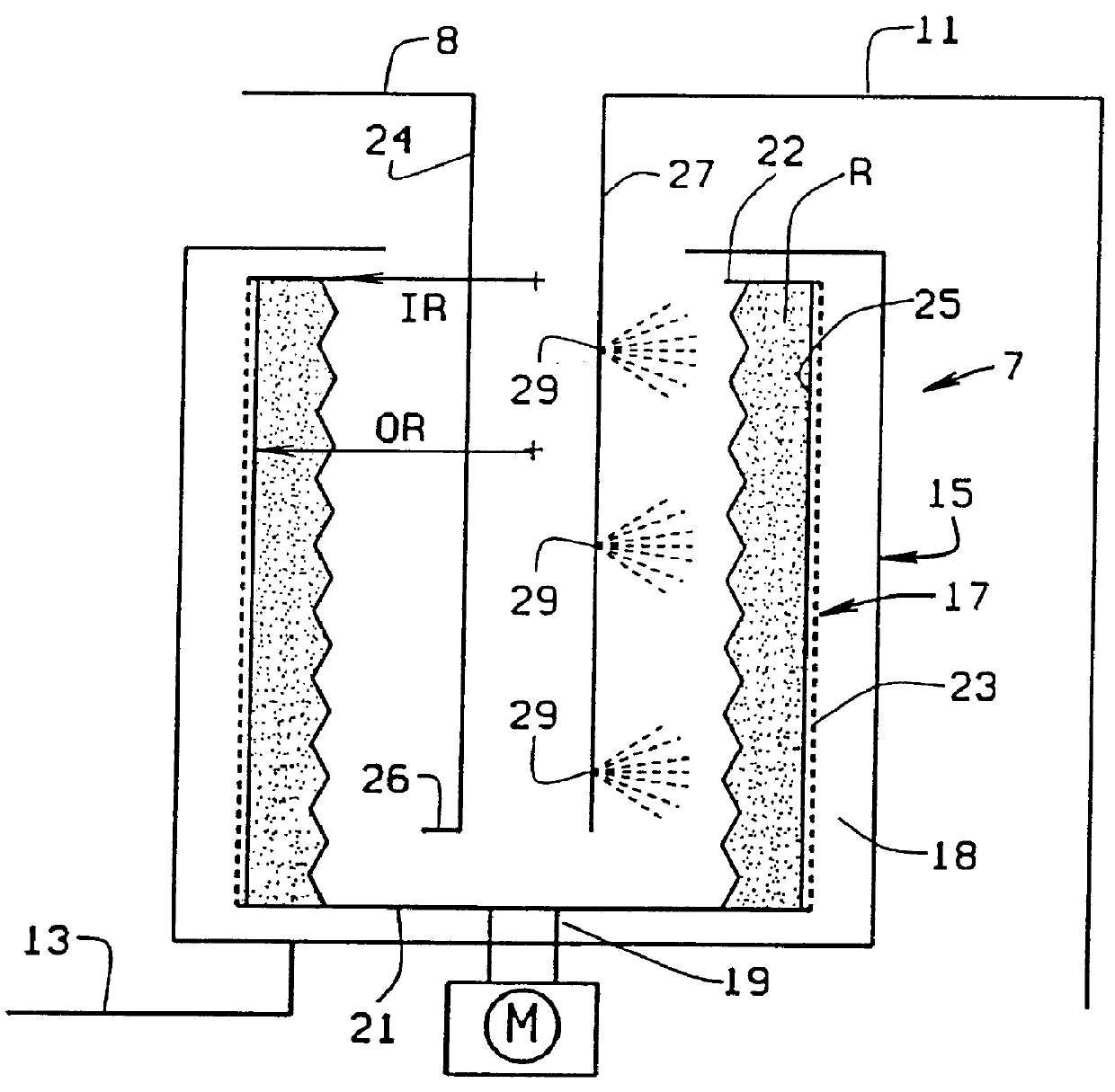
A number of design issues in the reactor development are unique to peptide synthesis.
In addition, these resins tend to be fairly soft in nature and, thus, are sensitive to physical attrition.
Deprotection of the resin-bound peptide must be complete in order to obtain the highest yield, but the resulting carbocations must not remain in contact with the peptide because of undesirable side-reactions that may occur.
Unfortunately, the time required to drain the solution from a resin
slurry suspension increases with the depth of the resin
bed formed during
filtration.
As a result, the
filtration times for
kilogram-scale reactions are far longer than those encountered in bench-scale reactions, so the risk of damage to the peptides due to reactions with carbocations increases with the batch size.
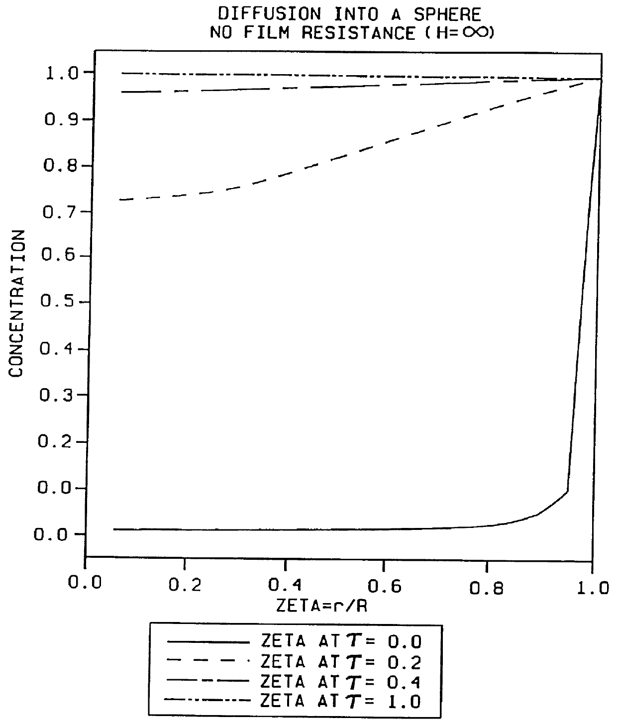
Increasing the fluid velocity relative to the resin reduces the
film resistance.
In extreme cases, one may find that
diffusion from the bulk
liquid phase to the free amines is impossible, and that the only boc-amino acid available for
coupling is the material initially present within the resin before the addition of DCC.
Stirred-tank reactors (STR's) are commonly used in peptide synthesis, but they suffer from certain limitations.
Because the beads are in suspension, the opportunities to increase the
liquid velocity relative to the particles in a stirred-tank reactor are extremely limited.
However, high flow rates create high pressures within the reactor, and the high pressures may have a detrimental effect upon the resin.
The use of packed beds, however, has its own set of problems.
The
packed bed, which has a height much greater than its
diameter, has a significant amount of wall surface area which impedes the expansion and contraction of the resin
bed.
A
high pressure thus is required to push all the wash through the
bed in the required amount of time.
This
high pressure can damage the resin beads, create fine particles which may block the filter, and potentially damage or break the filter
frit.
If
high pressure is not used, then flow through the bed will be too slow and the peptides may be allowed to react for too long and may undergo side reactions.
(1) Ignoring the problems with resin swelling. Verlunder, et al., U.S. Pat. No. 4,192,798 discloses approaches in which the reactor pressure drop is at least 200 psi, and up to 10,000 psi or more. They claimed quantitative yields, and that reactions which take hours in other reactors were completed in minutes. Difficulties with this type of reactor include degradation of the resin, blockage of the outlet
frit, maintaining a uniform axial flow throughout the column upon scale-up, inefficiencies in washing due to
dead volume, and the cost of the column and high-pressure pumps. This type of reactor is essentially an industrial-scale HPLC.
(2) Allowing axial expansion of the column. Baru, et al., WO 88 / 909010.6, SU 4117080 developed a zero
dead volume reactor in which one end of the reactor was allowed to float with the resin. A small weight was added to the top
piston of the reactor to provide a
constant force to the floating head of the reactor. As a result, the column was operated at a low pressure drop to avoid spilling
solvent out around the top head, making it very sensitive to blockage in the outlet
frit. Accumulation of DCU in the bed or within the frit which may increase the pressure drop and could have safety and environmental consequences. In addition, the low pressure drop constraint requires a low
liquid velocity, resulting in low Reynolds numbers and possible maldistribution of the liquid flow. The low liquid rates also result in longer
exposure times to the reactants and washes.
(3) Use of gel supported by a rigid
polymer. Atherton, et al., JCS Chemical Communications, p. 1151 , developed a rigid
polymer in which gel could be contained within the macropores. The gel could swell and shrink, but the volume of the rigid polymer beads would remain constant. As a result, high liquid flow rates, low pressure drops, and constant resin volume could be obtained. However, it is most likely that a reduction of
mass transfer will occur with these types of supported resins, since the dffusional path of the reactants would increase after adding film and pore
diffusion through the supports. In addition, these types of resins are expensive.
(4) Allowance for dead volume. Lapluye and Poisson, PCT publication no. WO 92 / 115867 developed a
piston-type reactor with fritted ends. In this type of reactor, resin is placed in a hollow
piston which is cycled upwards and downwards within a larger cylinder full of
solvent and reactants. This type of reactor is essentially similar to a
shaker or
fluidized bed reactor, and the mixing motion of the piston reactor should compensate for the differences in densities of the resin and the solvents. It appears that the efficiency of the washing should be the same as, or somewhat better than, smaller
fluid phase volumes than that in an STR. However, the volume of
solvent used relative to the resin
mass is probably considerably greater than that required by a typical tubular reactor. The Reynolds numbers are probably quite low, and it may be difficult to scale up the
mechanics. In addition, heat can be generated due to "
viscous dissipation" effects caused by the motion of the piston through the liquid, requiring some additional means of cooling.
The centrifugal forces cause the resin particles to form a bed on the inside walls of the basket, and cause a moderate degree of fluid recirculation through the resin bed.
The drag imposed upon the basket by the liquid bath imposes
high torque upon the
drive motor, and will also cause the generation of heat.
For these reasons, the rotational speed of the Birr reactor will be relatively slow and the relative fluid to solid velocity will be limited.
The limits on rotational speed will almost certainly result in a non-uniform resin bed that is shallow at the top and deep near the bottom.
As a result, the contact between the reactant rich liquid and resin will not be consistent throughout the reactor.
This will thus also require a significant volume of reactants relative to the resin
mass.
This large volume will result in the use of a low concentration solution, which consequently results in a slower
reaction rate and longer reaction time.
Also, little room is provided for expansion of the resin.
As a result of expansion and contraction, the
exposure of resin to the
liquid phase is likely to be non-uniform.
Complete and uniform contact and removal of liquid from the rotor may be very difficult to accomplish.

