

Filter medium for leukocyte removal, method of making, and method of using thereof
- Summary
- Abstract
- Description
- Claims
- Application Information
AI Technical Summary
Benefits of technology
Problems solved by technology
Method used
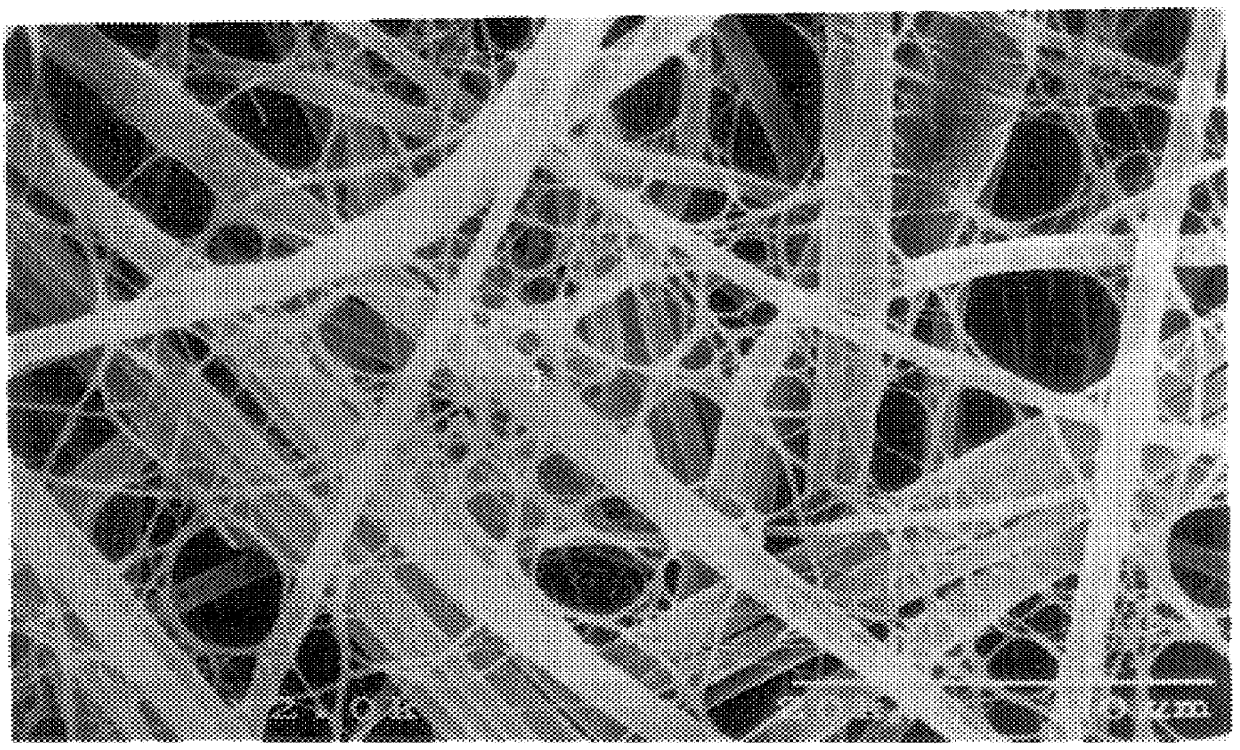
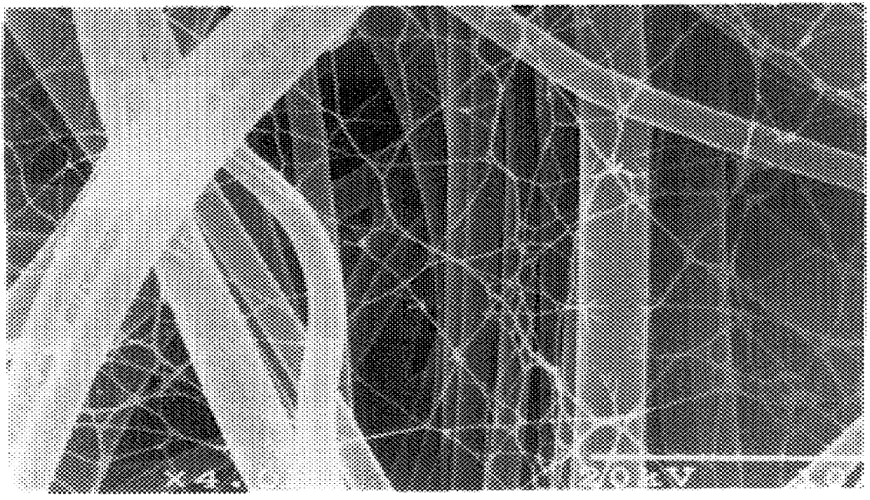
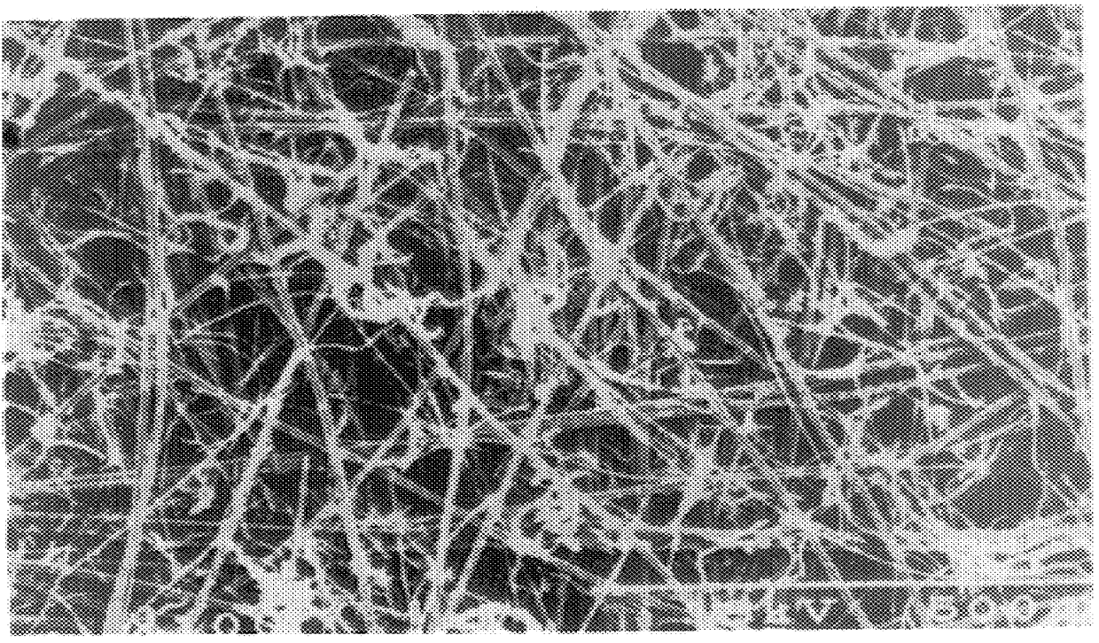
Image

Examples
example 2
The above fibers prepared in the same manner as in Example 1 were kept in the same manner as in Example 1 on the same porous element as used in Example 1 to prepare a filter material in which extremely fine fibers were kept on both surfaces on the front and back sides of the porous element. The extremely fine fibers kept had an average fiber diameter of 0.25 .mu.m; the ratio between the average pore diameter of the porous element and the average fiber diameter of the extremely fine fibers was 36.8; the ratio between the average fiber diameter of the porous element and the average fiber diameter of the extremely fine fibers was 4.8; the porosity of the filter material was 85% and the keeping proportion of the fiber structure to the filter material was 1.3% by weight. A laminate (0.26 g) of 7 sheets of this filter material was packed in a vessel having an effective sectional area of filtering portion of 9.0 cm.sup.2 (3.0 cm.times.3.0 cm) so that the packing density became 0.21 g / cm.su...
example 3
The same porous element as used in Example 1 was cut to a size of 25 cm.times.35 cm, immersed in 375 mL of a culture medium having an acetic acid bacterium concentration of 164 cells / mL and subjected in this state to stationary culture at 28.degree. C. for 14 hours. During the stationary culture, the porous element was turned upside down every two hours. After completion of the stationary culture, washing with a water stream was effected to remove the acetic acid bacteria. According to the above-mentioned production process, there was obtained a filter material in which a reticulate structure composed of cellulose fibers produced by the acetic acid bacterium having an average fiber diameter of 0.02 .mu.m were kept on the surfaces of the front and back sides of the porous element. As the acetic acid bacterium, there was used Acetobacter xylinum IFO13693). The composition of the culture medium was 2% of grape sugar, 0.5% of polypeptone, 0.5% of yeast extract, 0.27% of sodium hydrogenp...
example 4
To a high pressure liquid treatment was subjected a filter material in which the extremely fine fibers were kept on both surfaces of the front and back sides of a porous element which filter material had been obtained by subjecting to the same operation as in Example 1 the same porous element as used in Example 1 and extremely fine fibers prepared by cutting cuprammonium rayon yarn (Benberg.RTM. yarn of 40 d / 45 f manufactured by Asahi Kasei Kogyo K. K.) having a fiber diameter of about 10 .mu.m so that the fiber length became about 0.8 mm and subjecting the fibers to the same operation as in Example 1. That is to say, the above filter material was subjected to columnar stream treatment (15 kg / cm.sup.2) under the conditions that the nozzle diameter was 0.2 mm, the nozzle pitch was 5 mm, the number of nozzle lines was 18, the distance between web and nozzle was 30 mm, the number of revolutions of nozzle header was 150 rpm and the moving speed of filter material was 5 m / min to prepare ...
PUM
| Property | Measurement | Unit |
|---|---|---|
| Length | aaaaa | aaaaa |
| Fraction | aaaaa | aaaaa |
| Fraction | aaaaa | aaaaa |
Abstract
Description
Claims
Application Information