Modular pressure swing adsorption with energy recovery

a technology of modular pressure swing and adsorption, which is applied in the direction of separation process, dispersed particle separation, chemical apparatus and processes, etc., can solve the problems of inefficient use of applied energy, heavy load on machines, and high cost of adsorber pressure vessels, and achieve high frequency operation, high energy efficiency, and compact equipment

Inactive Publication Date: 2000-04-18
AIR PROD & CHEM INC
View PDF28 Cites 210 Cited by
  • Summary
  • Abstract
  • Description
  • Claims
  • Application Information

AI Technical Summary

Benefits of technology

The present invention is intended to enable high frequency operation of pressure swing and vacuum swing adsorption processes, with high energy efficiency and with compact equipment of low capital cost. The invention applies in particular to relatively low pressure processes conducted near atmospheric pressure, so that fluid sealing may be accomplished primarily by narrow clearances between revolving machine components and their housings.

Problems solved by technology

This conventional pressure swing adsorption process makes inefficient use of applied energy, because of irreversible expansion over the valves over large pressure differences while switching the adsorbent beds between higher and lower pressures.
In these and other prior art devices, the vacuum pumps are subject to varying pressure load over each pumping step on a bed, so that the machines are loaded severely by the cyclically changing duty as well as operating on average less efficiently than under true steady state conditions.
With relatively low PSA cycle frequencies attainable with conventional granular adsorbent beds, the adsorber pressure vessels are bulky and costly.
For large industrial PSA systems, mechanical immobilization of the adsorbent beds has not been practicable.
A further limitation to the use of finely granular adsorbent beds for PSA and other gas separation processes arises as increasingly smaller particle diameters are considered in order to reduce the macropore diffusion mass transfer resistance as required for higher frequency operation.
As operation of PSA processes at high frequencies requires small particle sizes to reduce the diffusional time constant, while the increased axial dispersion prevents a reduction of bed length commensurate with smaller particle diameter, performance tends to degrade due to high pressure drop and bed attrition problems.
However, a rotary adsorbent bed assembly based on these prior art devices may be impracticable for large PSA units, owing to the weight of the rotating assembly.
Also, when separating gas components which are highly inflammable or toxic, the rotary adsorbent bed assembly would need to be completely enclosed in a containment shroud to capture any leakage from large diameter rotary seals.
Conventional PSA systems have considerable dead volume associated with the volume of pressure vessel heads, flow distributors and conduit pipework between the ends of the adsorbent column and the directional valves controlling the PSA cycle steps.
Prior art rotary PSA devices also have considerable dead volume for flow distribution and collection, since the valve faces are again remote from the adsorbent bed ends.
This problem would become proportionately worse if operation at higher cycle frequency were contemplated, since flow distribution would become more critical.
These limitations would be especially severe for rotary PSA devices with radial flow through the adsorbent beds, and using either barrel or face valves whose valve surfaces are far separated from the adsorbers as illustrated by the devices of Boudet et al (U.S. Pat. No. 5,133,784), Petit et al (U.S. Pat. No. 5,441,559) and Schartz (PCT publication WO 94 / 04249).

Method used


Image

  • Modular pressure swing adsorption with energy recovery
  • Modular pressure swing adsorption with energy recovery
  • Modular pressure swing adsorption with energy recovery

Examples


Embodiment Construction

FIGS. 1, 2, 3 and 4

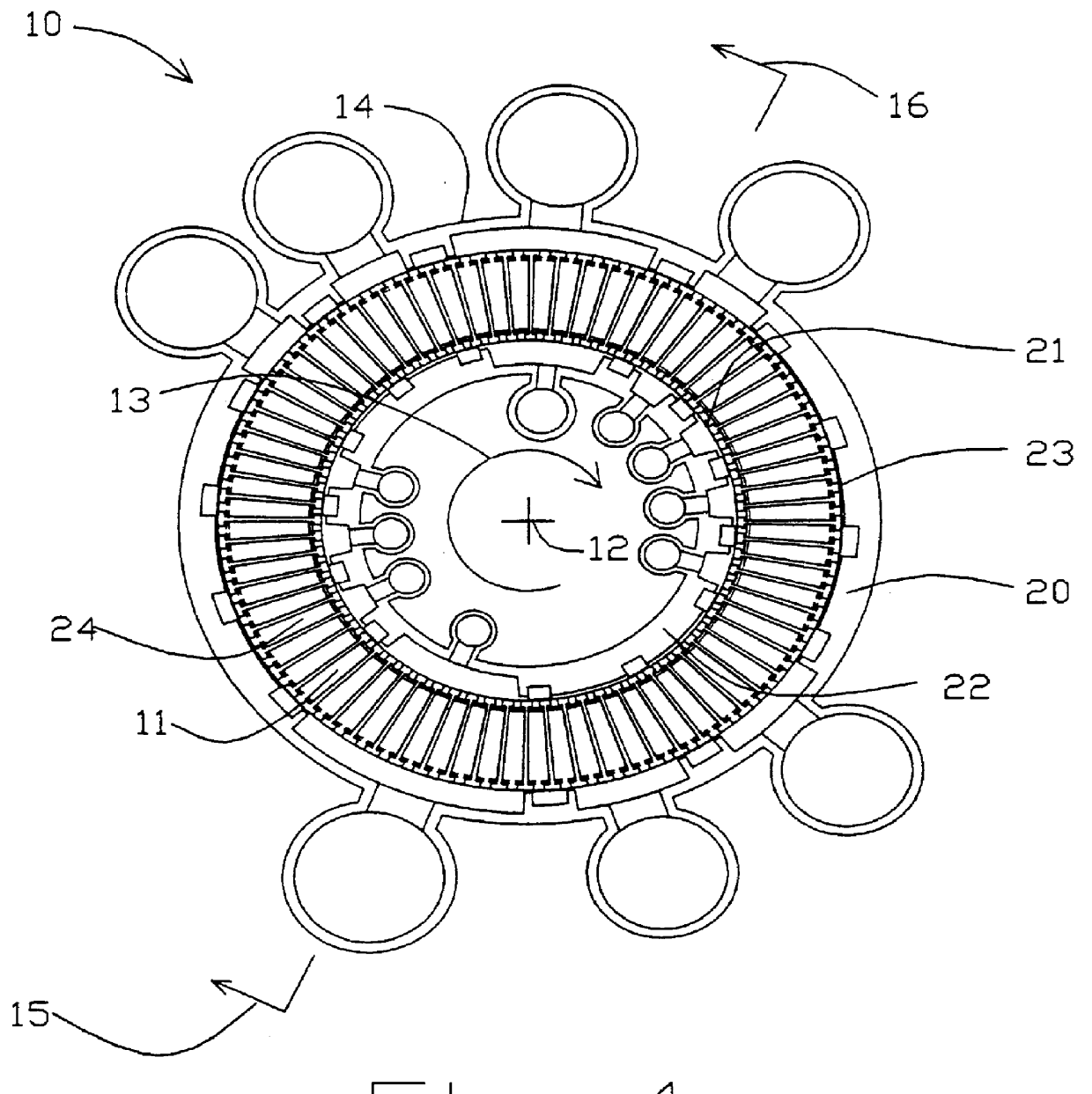
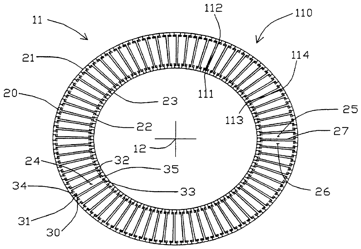
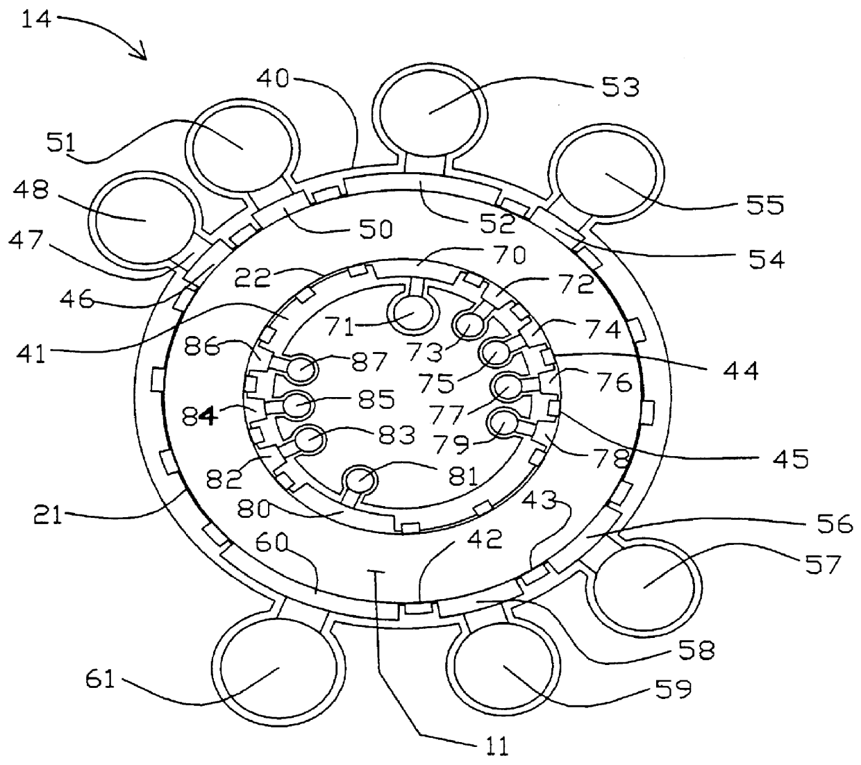
A module 10 according to the invention is shown in FIGS. 1, 2, 3 and 4. The module includes a rotor 11 revolving about axis 12 in the direction shown by arrow 13 within stator 14. FIG. 4 is an axial section of the module 10, defined by arrows 15 and 16 in FIG. 1. FIG. 1 is a cross-section of the module 10, defined by arrows 17 and 18 in FIG. 4. FIG. 2 is the sectional view of the rotor 11 repeated from FIG. 1, with the stator deleted for clarity. FIG. 3 is the sectional view of the stator 14 repeated from FIG. 1, with details of the rotor deleted for clarity.

In general, the apparatus of the invention may be configured for flow through the adsorber elements in the radial, axial or oblique conical directions relative to the rotor axis. For operation at high cycle frequency, radial flow is preferred, as expressed in the embodiment of module 10, so that the centripetal acceleration will lie parallel to the flow path for most favourable stabilization of buoyancy-driven...


PUM


Abstract

Pressure swing adsorption (PSA) separation of a feed gas mixture is performed within an apparatus having typically a single prime mover powering a feed compressor for one or multiple rotary PSA modules in parallel, each module including a rotor with a large number of angularly spaced adsorber elements, with valve surfaces between the rotor and a stator so that individual adsorber elements are opened to compartments for staged pressurization and blowdown, with thermally boosted energy recovery from staged expansion of countercurrent blowdown and light reflux gases, and a plurality of adsorber elements opened at any instant to each compartment so that each compressor and expander stage operates under substantially steady conditions of flow and pressure.

Description

The invention relates to gas separations conducted by pressure swing adsorption, and in particular applications to oxygen or nitrogen separation from air and to hydrogen purification.Gas separation by pressure swing adsorption (PSA) is achieved by coordinated pressure cycling and flow reversals over an adsorbent bed which preferentially adsorbs a more readily adsorbed component relative to a less readily adsorbed component of the mixture. The total pressure is elevated during intervals of flow in a first direction through the adsorbent bed from a first end to a second end of the bed, and is reduced during intervals of flow in the reverse direction. As the cycle is repeated, the less readily adsorbed component is concentrated in the first direction, while the more readily adsorbed component is concentrated in the reverse direction.A "light" product, depleted in the more readily adsorbed component and enriched in the less readily adsorbed component, is then delivered from the second e...

Claims


Application Information

Patent Timeline
Patent Type & Authority Patents(United States)
IPC IPC(8): B01D53/04B01D53/047
CPCB01D53/06B01D53/047B01D53/0462
Inventor KEEFER, BOWIE G.DOMAN, DAVID G.
Owner AIR PROD & CHEM INC
Why Eureka
Try Eureka