Organic positive temperature coefficient thermistor and manufacturing method therefor

a positive temperature coefficient and thermistor technology, applied in the direction of oxide conductors, conductors, non-metal conductors, etc., can solve the problems of inability to achieve sufficient ptc characteristics, inability to meet the requirements of overcurrent protection elements or temperature sensors in particular, and inability to achieve a sufficient resistance change ra

Inactive Publication Date: 2000-11-07
TDK CORPARATION
View PDF14 Cites 58 Cited by
  • Summary
  • Abstract
  • Description
  • Claims
  • Application Information

AI Technical Summary

Problems solved by technology

In this case, no sufficient PTC characteristics are often obtained.
However, the specific resistance value at room temperature is as high as 10.sup.4 .OMEGA.cm, and so is impractical for an overcurrent-protecting element or temperature sensor in particular.
A problem with carbon black is, however, that when an increased amount of carbon black is used to lower the initial resistance value, no sufficient rate of resistance change is obtainable; no reasonable tradeoff between low initial resistance and a large rate of resistance change is obtainable.
In this case, too, it is difficult to arrive at a sensible tradeoff between low initial resistance and a large rate of resistance change.
However, these thermistors are still insufficient in terms of hysteresis and so are unsuitable for applications such as temperature sensors, although the effect on the tradeoff between low initial resistance and a large resistance change is improved.
Although some thermistors have an operating temperature in the range of 60 to 90.degree. C., they are impractical because their performance becomes unstable upon repetitive operations.
When thermistors are used as protective elements for secondary batteries, electric blankets, heaters for lavatory seats and vehicle seats, etc., an operating temperature of 100.degree. C. or higher poses a great danger to the human body.
However, this thermistor is found

Method used


Image

  • Organic positive temperature coefficient thermistor and manufacturing method therefor
  • Organic positive temperature coefficient thermistor and manufacturing method therefor
  • Organic positive temperature coefficient thermistor and manufacturing method therefor

Examples


example 1

High-density polyethylene (HY 540 made by Nippon Polychem Co., Ltd. with an MFR of 1.0 g / 10 min. and a melting point of 135.degree. C.) was used as the polymer matrix, microcrystalline wax (Hi-Mic-1080 made by Nippon Seiro Co., Ltd. with a melting point of 83.degree. C.) as the low-molecular organic compound, and filamentary nickel powders (Type 255 Nickel Powder made by INCO Co., Ltd.) as the conductive particles. The conductive particles had an average particle diameter of 2.2 to 2.8 .mu.m, an apparent density of 0.5 to 0.65 g / cm.sup.3, and a specific surface area of 0.68 m.sup.2 / g.

The high-density polyethylene was milled with the nickel powders at a weight of four times as large as the polyethylene in a mill at 150.degree. C. for 5 minutes. The mixture was further milled with the addition thereto of the wax at a weight of 1.5 times as large as the polyethylene and the nickel powders at a weight of 4 times as large as the wax. For a further 60 minutes, the mixture was milled toge...

example 2

A thermistor element was obtained as in Example 1 with the exception that paraffin wax (HNP-10 made by Nippon Seiro Co., Ltd. with a melting point of 75.degree. C.) was used as the low-molecular, water-insoluble organic compound. A temperature vs. resistance curve was obtained and accelerated testing was carried out as in Example 1.

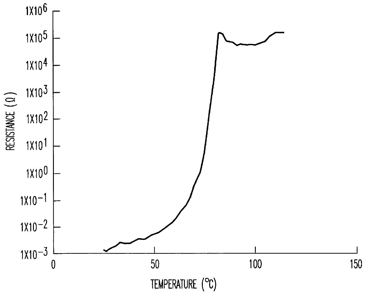
This element had a resistance value of 2.0.times.10.sup.-3 .OMEGA. (1.6.times.10.sup.-2 .OMEGA.cm) at room temperature (25.degree. C.), and showed a sharp resistance rise at around 75.degree. C. with a maximum resistance value of 7.7.times.10.sup.6 .OMEGA. (6.0.times.10.sup.7 .OMEGA.cm) and a rate of resistance change of 9.6 orders of magnitude.

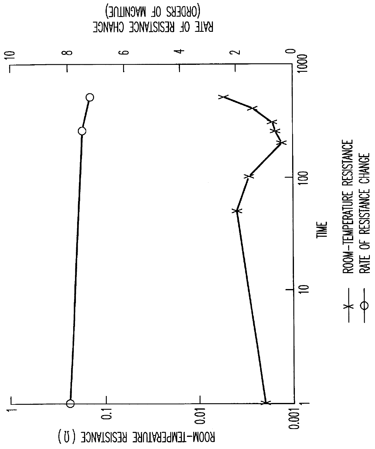
In the 80.degree. C. and 80% RH accelerated testing, the room-temperature resistance value was 6.2.times.10.sup.-3 .OMEGA. (4.9.times.10.sup.-2 .OMEGA.cm) after the elapse of 500 hours, with the rate of resistance value being 8.7 orders of magnitude. Thus, both the room-temperature resistance value and the rate of ...

example 3

A thermistor element was obtained as in Example 1 with the exception that high-density polyethylene (HY420 made by Nippon Polychem Co., Ltd. with an MFR of 0.4 g / 10 min. and a melting point of 134.degree. C.) was used as the polymer matrix. A temperature vs. resistance curve was obtained and accelerated testing was carried out as in Example 1.

This element had a resistance value of 4.0.times.10.sup.-3 .OMEGA. (3.1.times.10.sup.-2 .OMEGA.cm) at room temperature (25.degree. C.), and showed a sharp resistance rise at around 75.degree. C. with a maximum resistance value of 6.0.times.10.sup.4 .OMEGA. (4.7.times.10.sup.5 .OMEGA.cm) and a rate of resistance change of 7.2 orders of magnitude.

In the 80.degree. C. and 80% RH accelerated testing, the room-temperature resistance value was 7.5.times.10.sup.-3 .OMEGA. (5.9.times.10.sup.-2 .OMEGA.cm) after the elapse of 500 hours, with the rate of resistance value being 6.5 orders of magnitude. Thus, both the room-temperature resistance value and t...


PUM


Abstract

An organic positive temperature coefficient thermistor comprising a thermoplastic polymer matrix, a low-molecular organic compound having a melting point that is equal to or greater than 40 DEG C. and less than 100 DEG C. and conductive particles, each having spiky protuberances, is obtained by crosslinking a milled mixture of these components with a silane coupling agent comprising a vinyl group or a (meth)acryloyl group and an alkoxy group. This organic positive temperature coefficient thermistor has sufficiently low resistance at room temperature and a large rate of resistance change between an operating state and a non-operating state, and can be operated at less than 100 DEG C. with a reduced temperature vs. resistance curve hysteresis, ease of control of operating temperature, and high performance stability.

Description

1. Prior ArtThe present invention relates to an organic positive temperature coefficient thermistor that is used as a temperature sensor or overcurrent-protecting element, and has PTC (positive temperature coefficient of resistivity) characteristics that its resistance value increases with increasing temperature.2. Background ArtAn organic positive temperature coefficient thermistor having conductive particles dispersed in a crystalline polymer has been well known in the art, as typically disclosed in U.S. Pat. Nos. 3,243,753 and 3,351,882. The increase in the resistance value is believed to be due to the expansion of the crystalline polymer upon melting, which in turn cleaves a current-carrying path formed by the conductive fine particles.An organic positive temperature coefficient thermistor can be used as a self control heater, an overcurrent-protecting element, and a temperature sensor. Requirements for these are that the resistance value is sufficiently low at room temperature ...

Claims


Application Information

Patent Timeline
IPC IPC(8): H01C7/02
CPCH01C7/027
Inventor HANDA, TOKUHIKOYOSHINARI, YUKIE
Owner TDK CORPARATION
Why Eureka
Try Eureka