Plasma processing system

a processing system and plasma technology, applied in the field of plasma processing system, can solve the problems of inability to achieve radially uniform plasma with the above helical resonator plasma source, inability to solve the above problem,

Inactive Publication Date: 2001-05-01
ANELVA CORP
View PDF4 Cites 24 Cited by
  • Summary
  • Abstract
  • Description
  • Claims
  • Application Information

AI Technical Summary

Benefits of technology

An object of the present invention is to provide a helical resonator plasma source that yields a radially uniform plasma in the downstream and which eliminates the localized sputtering of the dielectric tube wall.

Problems solved by technology

In this respect, conventional high density plasma sources have limited applications owing to their design rules.
First, a major problem concerning the configuration of the above-mentioned high density plasma source making the helical resonator plasma is in the controllability of radial plasma uniformity.
Even though a large-diameter dielectric tube is used instead of the dielectric tube 52, the above problem can not be solved.
Thus, without additional hardware, for example, magnetic multipole confinement, a radially uniform plasma can not be obtained with the above helical resonator plasma source.
This causes a contamination of the plasma.
Because of these qualities, the conventional helical resonator plasma source has limited application in plasma assisted wafer processing, especially in large-area wafer processing.

Method used


Image

  • Plasma processing system
  • Plasma processing system
  • Plasma processing system

Examples


working example 2

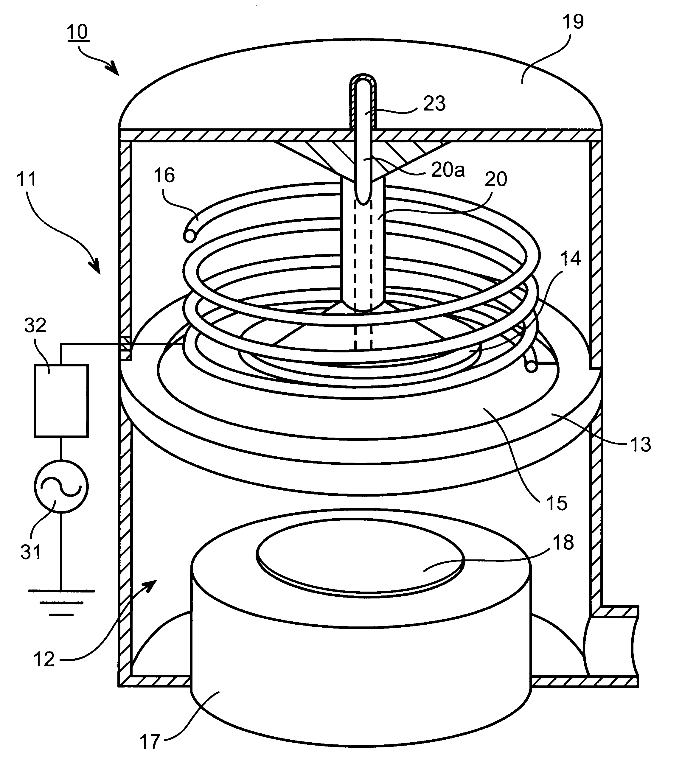
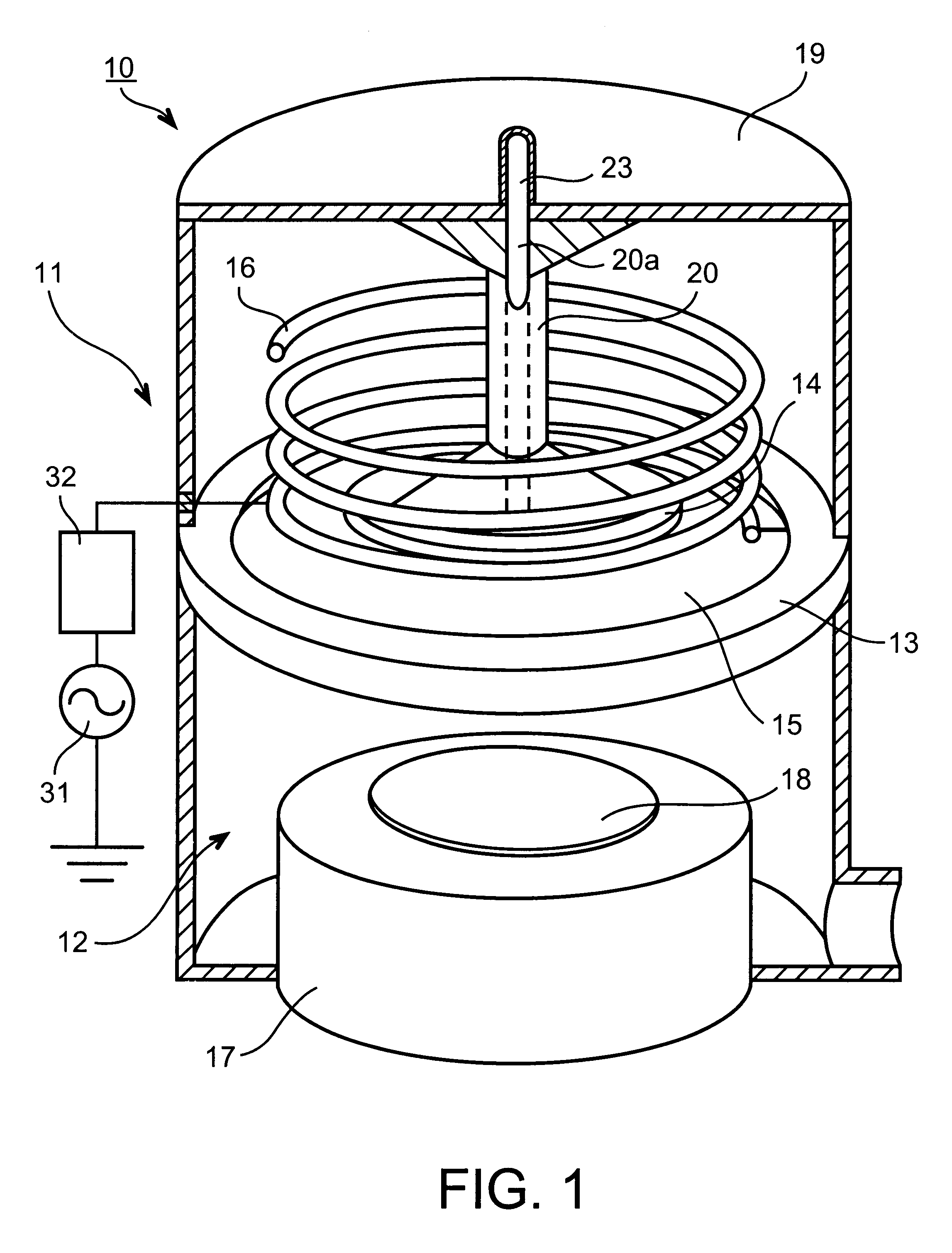
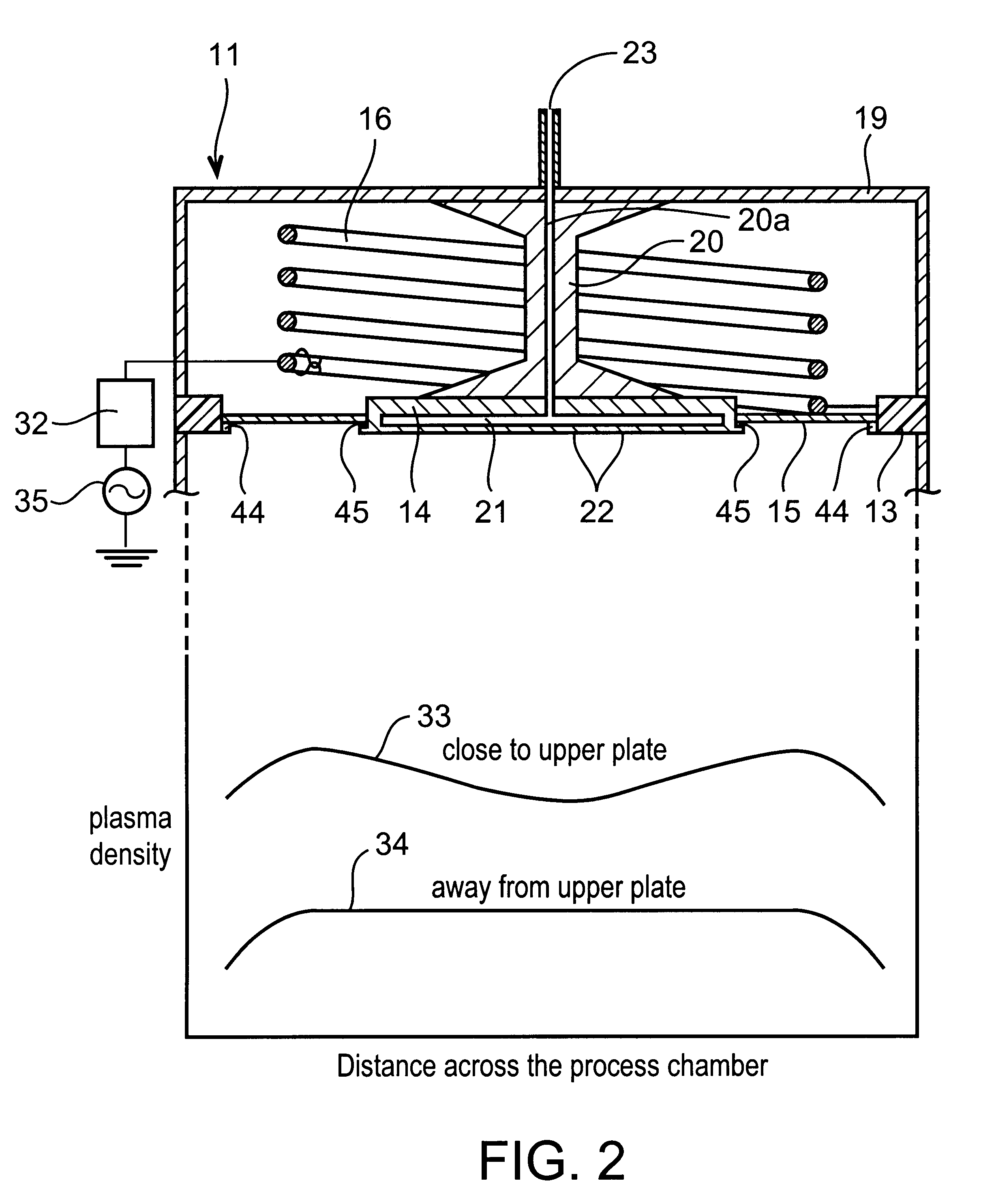
A working example 2 will be explained in accordance with FIG. 3, where only the resonator section is shown. In FIG. 3, components which are substantially identical to the components explained in the working example 1 are respectively designated with the same reference numerals. The resonator 11 and the process chamber 12 in the working example 2 are the same as given in the working example 1 in the view of the hardware configuration. The only difference is that the rf power source 31 with a constant operating frequency used in the working example 1 is replaced by a variable frequency rf power source 35 and the matching circuit 32 is eliminated. The variable frequency range around a frequency selected in the variable frequency rf power source 35 may usually be in the range of .+-.10 MHZ. The selected frequency usually is in the range of 1-40 MHz, typically being selected as 13.56 MHZ. Other properties of the rf power source are the same as that explained in the working example 1. Use...

working example 3

A working example 3 will be explained in accordance with FIG. 4, where only the resonator section is shown. FIG. 4 shows a schematic view of the working example 3. In FIG. 4 components which are substantially identical to the components explained in the working example 1 are respectively designated with the same reference numerals. In the working example 3, the top plate 19 is placed on a dielectric ring 36 in order to set the central metal plate 14 in a floating state, which is electrically connected to the top plate 19. Except for the addition of this dielectric ring 36 the configuration of the resonator 11 is almost the same as the working examples 1 and 2. However, in order to prevent the propagation of electromagnetic radiation to the outside, a metal case 37 is attached to cover the upper section of the resonator. The rf electrical power to the helical coil 16 may come from the rf power source 31 given in the working example 1, or the variable frequency rf power source 35 give...

working example 4

Working example 4 will be explained in accordance with FIG. 5 where only the resonator section is shown. FIG. 5 shows a schematic view of the working example 4. The working example 4 is an extension of the working example 3. In FIG. 5, components which are substantially identical to the components explained in the working example 3 are respectively designated with the same reference numerals. In the working example 4, an L-C circuit 38 is electrically connected to the top plate 19, which in turn is electrically connected to the central metal plate 14. Usually the L-C circuit 38 is comprised of an inductor 39 and a variable capacitor 40 which are connected in series, so that the resonance frequency of the L-C circuit 38 can be changed to be equal to the frequency of the rf power applied to the helical coil 16. When the resonance frequency of the L-C circuit 38 is equal to the frequency of applied rf power, an rf current flows through the central metal plate 14 to the ground. Further,...


PUM

PropertyMeasurementUnit
constant frequencyaaaaaaaaaa
pressureaaaaaaaaaa
impedanceaaaaaaaaaa

Abstract

A plasma processing reactor includes a helical resonator including a top plate and a helical coil, the helical coil is made of a metal with a length of lambd/4, wherein n is an integer and lambd is a wavelength of rf frequency applied to the helical coil. The reactor also includes a plasma process chamber including a wafer holder arranged at a lower position therein and a wafer to be processed is loaded on the wafer holder. The helical resonator has a vertical bar for introducing a gas, the vertical bar is fixed to the top plate of the helical resonator and is connected to a gas inlet port. A partition wall separates the helical resonator and the plasma process chamber. The partition wall includes an outer metal ring, a circular central metal plate, and a doughnut-shaped dielectric plate between the outer metal ring and the central metal plate, the doughnut-shaped dielectric plate having an inner diameter and an outer diameter. The central metal plate is fixed to the top plate using the vertical bar and includes a gas reservoir and a plurality of gas inlet ports. The helical coil is placed around the vertical bar, and the helical coil has a diameter that is greater than the inner diameter of the doughnut-shaped dielectric plate and is smaller than the outer diameter of the doughnut-shaped dielectric plate.

Description

The present application corresponds to and claims the priority of Japanese Patent Application No. 11-56067, filed in Japan on Mar. 3, 1999, and the entire contents of which are hereby incorporated herein by reference.1. Field of Industrial ApplicationThe present invention relates to a plasma processing system having an improved plasma source capable of supplying ions, electrons, neutral radicals and ultra-violet and visible light useful for chemical vapor disposition (CVD) or etching processes in the fabrication of devices on semiconductor wafers in semiconductor industry.2. Discussion of Related ArtPlasma sources are an indispensable tool for the present and future semiconductor wafer processing in semiconductor industry. Three important conditions of such sources are higher plasma density, higher radial uniformity of the plasma over the wafer surface, and large-area plasma. In this respect, conventional high density plasma sources have limited applications owing to their design ru...

Claims


Application Information

Patent Timeline
Patent Type & Authority Patents(United States)
IPC IPC(8): H01J37/32H05H1/46
CPCH01J37/32082H01J37/3211H05H1/46H01J37/32091H01L21/67017
Inventor WICKRAMANAYAKA, SUNIL
Owner ANELVA CORP
Why Eureka
Try Eureka