SOG dispensing system and its controlling sequences

a technology of dispensing system and control sequence, applied in the field of sog (, can solve the problems of unsatisfactory effects, difficulty in clearing photoresist inside the void, and quality control issue of ild

Inactive Publication Date: 2001-06-12
PROMOS TECH INC
View PDF3 Cites 33 Cited by
  • Summary
  • Abstract
  • Description
  • Claims
  • Application Information

AI Technical Summary

Benefits of technology

It is therefore an object of the present invention to provide a new SOG dispensing system and its controlling sequences allowing for continuous production.

Problems solved by technology

It is well known that uneven (non-planar) surface topology of a wafer can cause undesirable effects and difficulties in the application of subsequent layers and fabrication processes such as pattern distortion after developing due to a focusing problem in a photolithography process, it becoming more serious at a recessed area because of insufficient exposure, Especially at a multilevel metallization structure, an interlevel dielectric (hereinafter referred as ILD ) is not only used as a dielectric layer but a planarizing layer to eliminate voids formed at gaps between metal conduction lines.
During a photolithography process, if there are voids formed, photoresist would flow into these voids and thus the thickness of photoresist isn't thick enough to protect the ILD layer during etching process and causes a quality-controlled issue of ILD.
Besides, it is hard to clear photoresist inside the voids and thus causes a wafer-contaminated problem so as to reduce production yield.
Thus, the SOG dispensing system must be idle when changing the SOG bottle 11, thereby prolonging fabrication cycle time, as well as raising fabrication cost because of unused residue of the SOG bottle.
Since in order to issure that there are no bubbles or particles in these dispensing lines, a dummy dispensing of a test running for particles and thickness confirmation is necessary after changing the SOG bottle, idle time of the SOG dispensing system is further prolonged and thus considerably lowers its operating efficient.

Method used


Image

  • SOG dispensing system and its controlling sequences
  • SOG dispensing system and its controlling sequences

Examples


Embodiment Construction

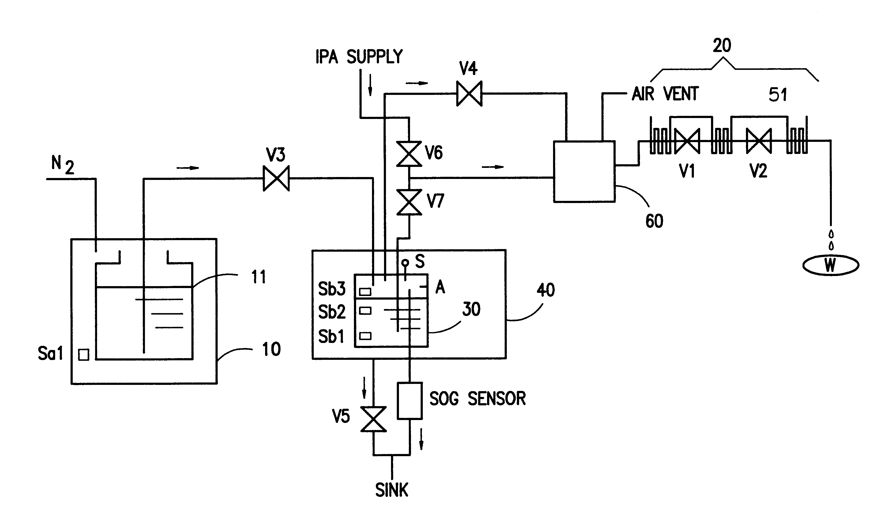
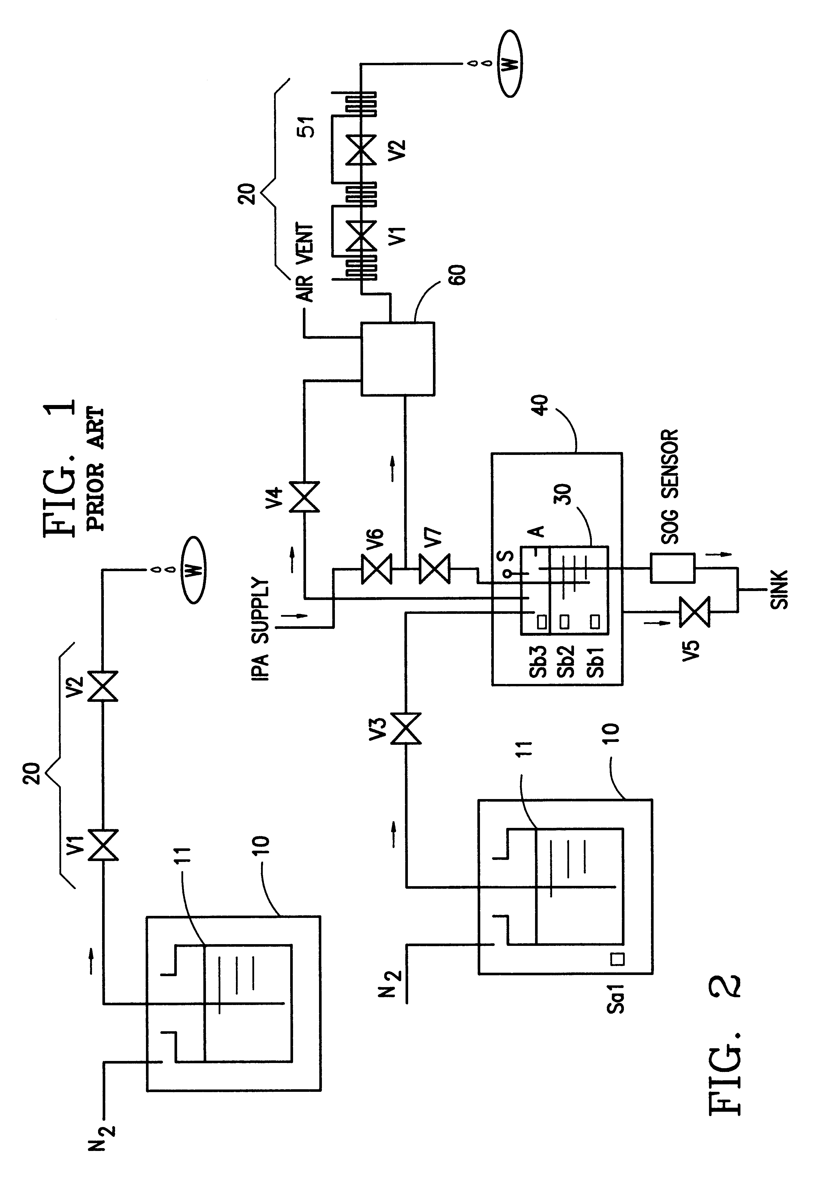
As aforementioned, the SOG bottle is partially expended in a test running for particles and thickness confirmation and then in a real SOG coating process for three lots of wafers (i.e. 150 wafers) so that only about 100 cc of SOG is finally left. Since this 100 cc of SOG is insufficient for a next lot, it can't be used due to its contaminating another SOG bottle and should be thrown away, thereby not only interrupting coating process but increasing expense cost of SOG. In order to overcome these problems, a new SOG dispensing system, according to the present invention, is proposed and its operating principles are that a buffer tank, whose wall is set three level sensors at different level heights, is connected between the source tank and the coating unit of prior art and that said residual SOG of the SOG bottle can be supplied into the buffer tank for a time interval by a control signal from one of these level sensors.

FIG. 2 is a SOG dispensing system of the present invention, where...


PUM

PropertyMeasurementUnit
temperatureaaaaaaaaaa
volumesaaaaaaaaaa

Abstract

The present invention relates to a SOG (Spin-On-Glass) dispensing system and its controlling sequences and, more particularly, to a SOG dispensing system allowing for continuous production and its controlling sequences According to the present invention, a buffer tank, whose wall is set a plurality of level sensors at different level heights, is connected between a source tank with a SOG bottle inside and a coating unit of prior art and then SOG is supplied for a time interval from the source tank into the buffer tank by control signals from these level sensors. Besides, the buffer tank is surrounded with a cooling unit to provide a low temperature enviroment allowing for prolonging life time of SOG and preventing organic solvent inside SOG from evaporating and then crystallizing to form contamination particles at wall of the SOG dispensing system. Thus, the resultant SOG dispensing system, according to the present invention, can resolve a shortcoming of discontinuous production of prior art due to a need for changing the SOG bottle, as well as another shortcoming of residue of the SOG bottle, thereby considerably raising operating efficient of the dispensing system by reducing its idle time and lowering fabrication cost by saving a SOG waste.

Description

1. Field of the InventionThe present invention relates to a SOG (Spin-On-Glass, hereinafter referred as SOG) dispensing system and its controlling sequences and, more particularly, to a SOG dispensing system allowing for continuous production and raising its operating efficient.2. Description of the Prior ArtBefore we start to introduce a SOG dispensing system of prior art, it is necessary to explain importance of SOG for a semiconductor device and its fabrication processes. It is well known that uneven (non-planar) surface topology of a wafer can cause undesirable effects and difficulties in the application of subsequent layers and fabrication processes such as pattern distortion after developing due to a focusing problem in a photolithography process, it becoming more serious at a recessed area because of insufficient exposure, Especially at a multilevel metallization structure, an interlevel dielectric (hereinafter referred as ILD ) is not only used as a dielectric layer but a pl...

Claims


Application Information

Patent Timeline
Patent Type & Authority Patents(United States)
IPC IPC(8): H01L21/00B05C11/08
CPCH01L21/6715B05C11/08
Inventor LIANG, MIKEBAW, PETERCHIU, JOHNCHANG, BRYAN
Owner PROMOS TECH INC
Why Eureka
Try Eureka