

Ftheta lens
a technology of theta and lens, applied in the field of ftheta lenses, can solve the problems of weak points, weak points, weak points of materials, etc., and achieve the effect of improving the quality of materials and reducing the cost of materials
- Summary
- Abstract
- Description
- Claims
- Application Information
AI Technical Summary
Benefits of technology
Problems solved by technology
Method used
Image

Examples
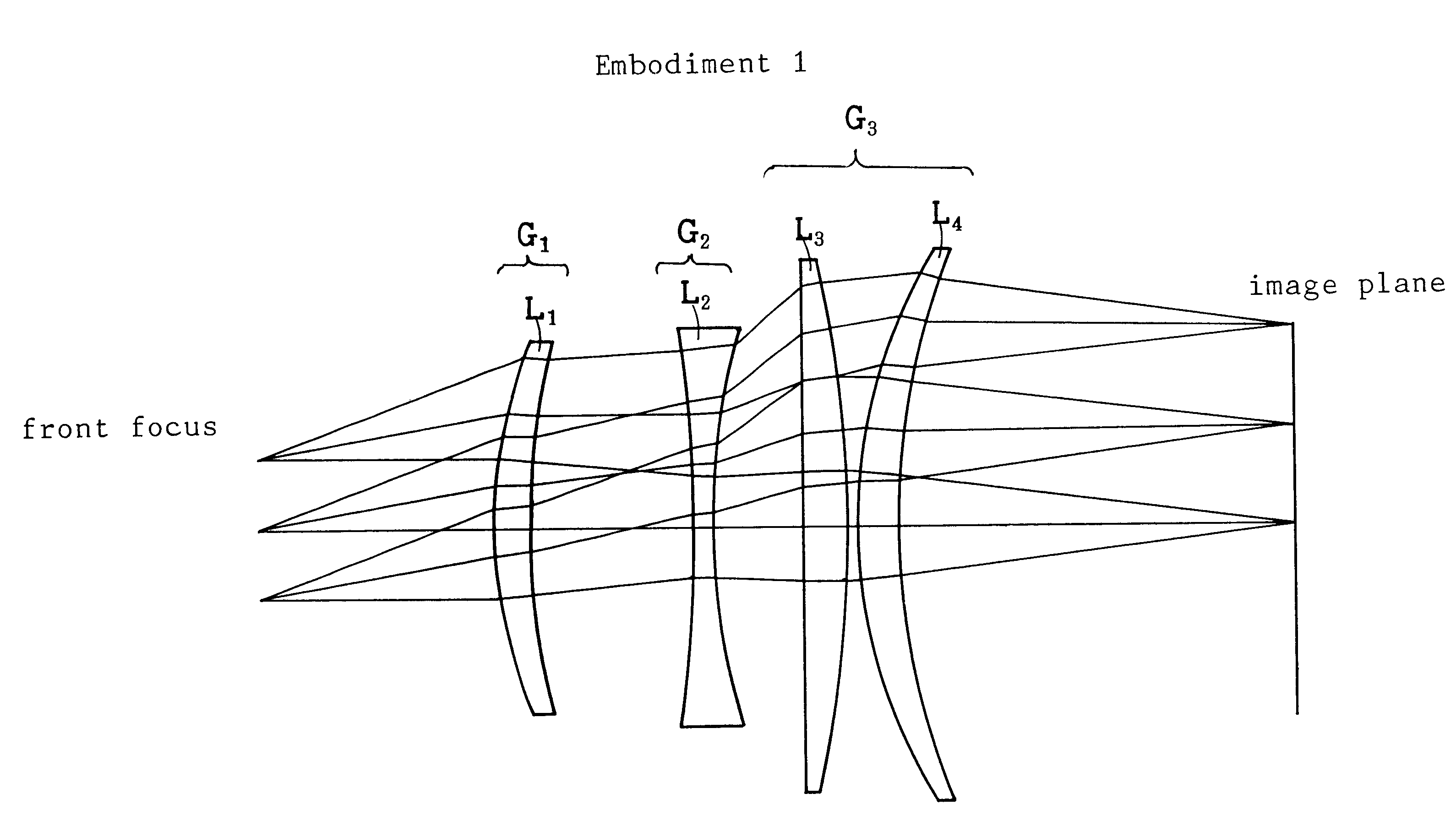
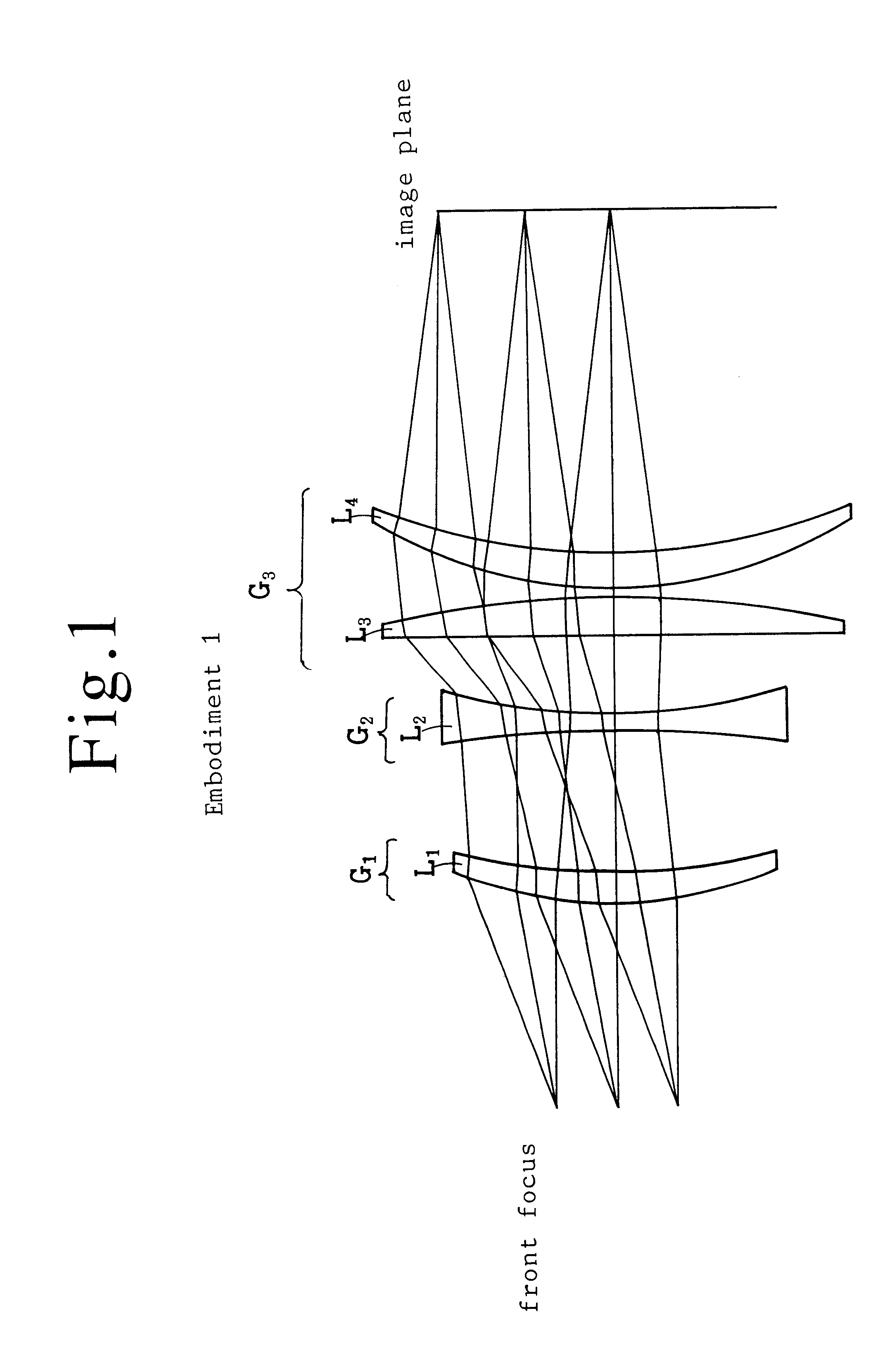
embodiment 1
assumes the whole focal length to be f=100 mm. The second group has a short focal length f.sub.2 =-63 mm. A short focal length signifies a large curvature. In the embodiment, f.sub.2 / f=-0.63 which lies in the above-mentioned range (31) between -2.2.ltoreq.f.sub.2 / f.ltoreq.-0.3.
The third lens group aligns two positive lenses L.sub.3 and L.sub.4 in series. L.sub.3 seems a plano-convex lens. But the front surface S.sub.5 is concave a little. L.sub.3 seems a thin lens but has a strong refractive power because of a Ge lens. Ge has a big coefficient (n-1)=3.003 which is seven times as big as (n-1)=0.4 of quartz. This means that L.sub.3 has the same refraction power as the quartz lens having a seven times larger curvature. .rho..sub.1 =-3994.603 mm and .rho..sub.2 =-217.271 mm give L.sub.3 a short focal length 76.5 mm. Another lens L.sub.4 of the third group is a positive meniscus lens. L.sub.4 is made of ZnSe (n=2.403). L.sub.4 has a focal length long 274 mm, since .rho..sub.1 =93.960 m...
embodiment 2
(all aspherical four lenses (FIG. 5 to FIG. 8))
An assembly of four aspherical lenses can realize this invention. FIG. 5 shows the lens composition of Embodiment 2. FIG. 6 denotes the spherical aberration. FIG. 7 shows the astigmatism. FIG. 8 exhibits the f.theta. property.
As explained before, the use of aspherical lenses enhances the freedom of design and facilities the cancellation of aberration. Embodiment 2 uses four lenses L.sub.1, L.sub.2, L.sub.3 and L.sub.4 which all have at least one aspherical surface. Table 2 denotes the parameters of Embodiment 2. Aspherical surfaces are assigned to the image-side surface S.sub.2 of L.sub.1, the image-side surface S.sub.4 of L.sub.2, the image-side surface S.sub.6 of L.sub.3 and the object-side surface S.sub.7 of L.sub.4. Table 3 shows the aspherical coefficients of Embodiment 2.
TABLE 3
Among four lenses, the first lens L.sub.1, the second lens L.sub.2 and the fourth lens L.sub.4 are made of zinc selenide ZnSe of n=2.403. The third lens L....
embodiment 3
uses four lenses L.sub.1, L.sub.2, L.sub.3 and L.sub.4. L.sub.1 and L.sub.2 have aspherical surfaces. The image-side S.sub.2 of L.sub.1 and the image-side S.sub.4 of L.sub.2 are aspherical. The other surfaces are spherical. Table 4 shows the lens parameters of Table 5 exhibits the aspherical coefficients.
TABLE 4
Among four lenses, the first lens L.sub.1, the second lens L.sub.2 and the fourth lens L.sub.4 are made of zinc selenide (ZnSe) of n=2.403. The third lens L.sub.3 is made of germanium (Ge) of n=4.003. The focal lengths and the distance are f=100 mm, f.sub.2 =-72 mm, f.sub.3 =62 mm and d=227 mm. Thus, the normalized focal lengths and the normalized distance are f.sub.2 / f=-0.72, f.sub.3 / f=0.62 and d / f =2.27. These parameters lie in the scopes defined by the conditions (a) to (c). The parameter d / f=2.27 exists near the upper limit (2.4). The spherical aberration is somewhat big. The field curvature .DELTA.M on the meridional direction takes the maximum 0.18 at 12 degrees. Oth...
PUM
| Property | Measurement | Unit |
|---|---|---|
| diameter | aaaaa | aaaaa |
| wavelength | aaaaa | aaaaa |
| wavelength | aaaaa | aaaaa |
Abstract
Description
Claims
Application Information