Composite monolithic elements and methods for making such elements

a monolithic element and composite technology, applied in the field of composite monolithic elements and methods for making such elements, can solve the problems of low yield in the manufacturing process, relative fragility, and high cost of materials,

Inactive Publication Date: 2001-12-11
SURFACE IGNITER CORP
View PDF6 Cites 20 Cited by
  • Summary
  • Abstract
  • Description
  • Claims
  • Application Information

AI Technical Summary

Problems solved by technology

This type of igniter has had wide spread commercial success, but is relatively fragile and includes a number of manufacturing

Method used


Image

  • Composite monolithic elements and methods for making such elements
  • Composite monolithic elements and methods for making such elements

Examples


first embodiment

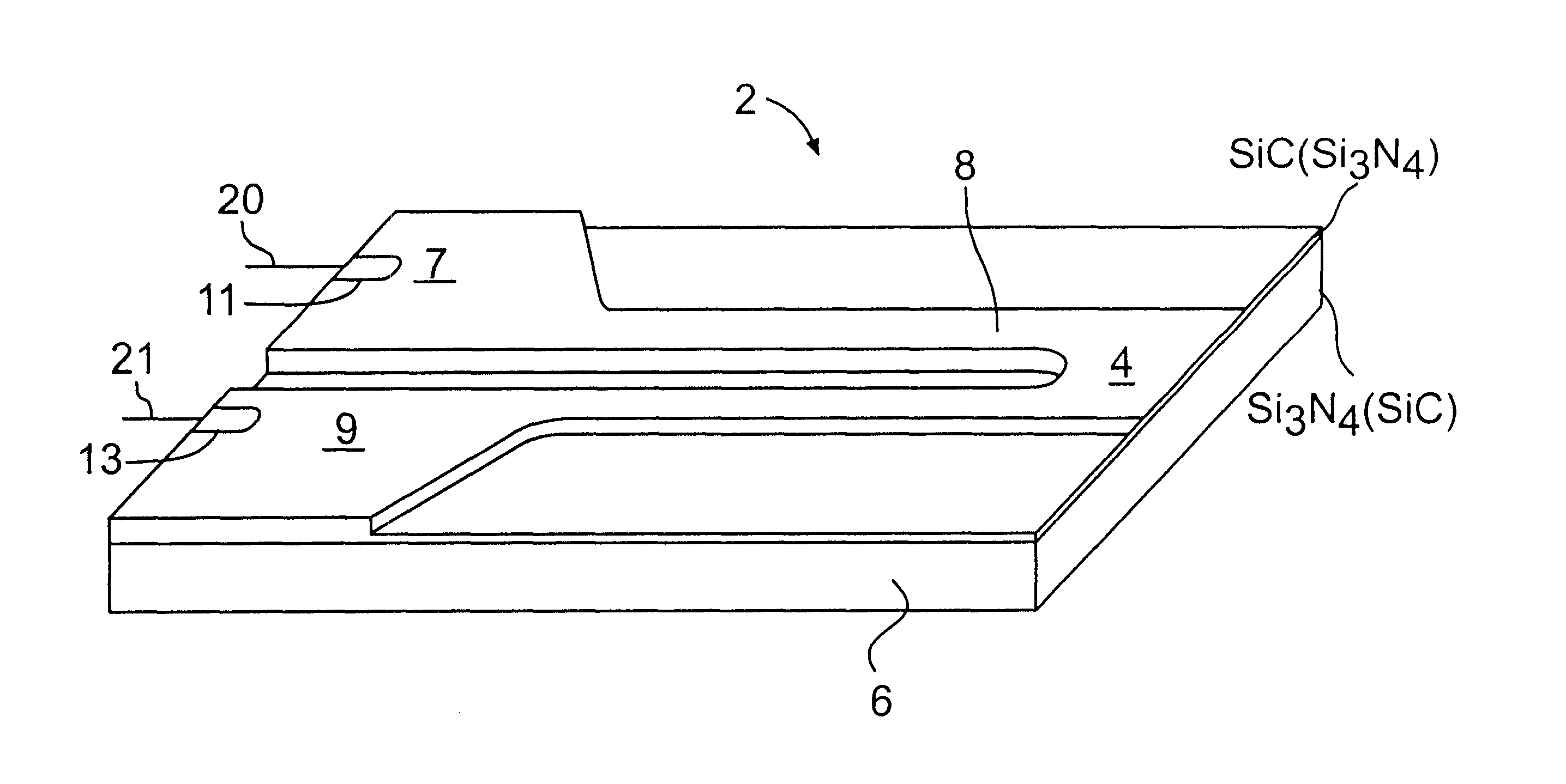
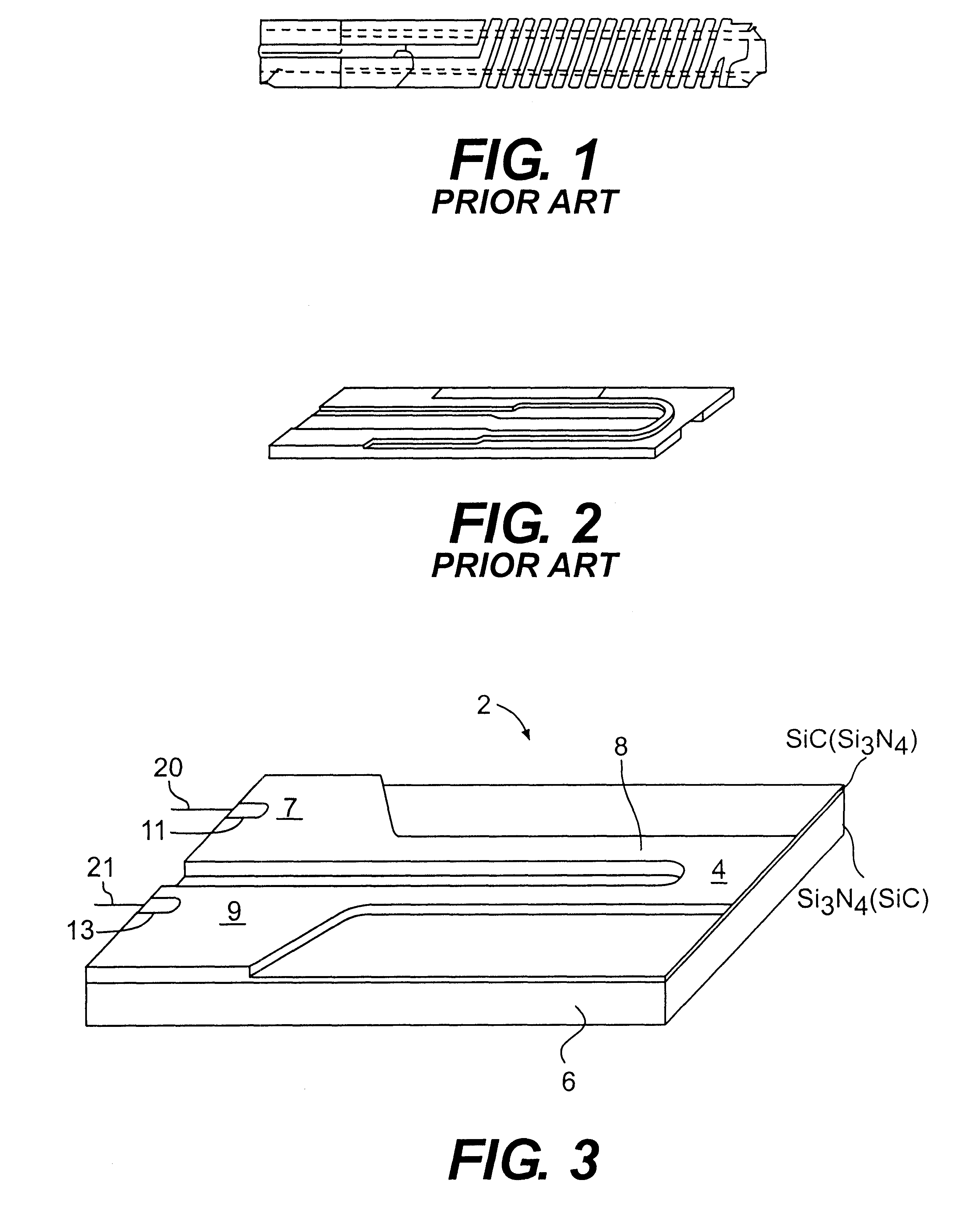
A composite monolithic heating element or igniter 2 in accordance with the invention is shown in FIG. 3. As illustrated, the igniter 2 includes a first region or layer 4 which has a first specific property. For example, in this embodiment of the invention, the first region or layer 4 act as a conductor or hot portion of the igniter 2. The igniter 2 also includes a second region or layer 6 which has a second specific property which is different than the specific property of the first layer 4. For example, the second layer 6 may act as an insulator and at the same time provides a physical support for the conductive layer 4.

An important feature of the present invention resides in the bonding together of the first and second layers 4 and 6 with a joint free bond to thereby form a mechanically continuous structure. This formation of a joint free mechanically continuous structure allows for the use of an extremely thin conductive layer 4. This feature i.e. the relatively thin conductive l...

example 1

A process for making a monolithic composite element in accordance with the present invention includes the step of providing a first mass of inorganic particles. These inorganic particles which may for example comprise a mix of silicon carbide and silicon nitride are utilized in a finely divided form. The preferred silicon carbide and silicon nitride materials have an average particle size of from about less than 0.10 to about 10 microns (greater than about 19 m.sup.2 / gm to about 0.6 m.sup.2 / gm) with a maximum size of about 50 microns (0.1 m.sup.2 / gm).

The first mass of inorganic, preferably ceramic particles is then mixed with an organic thermoplastic molding compound such as a wax and up to about 5% by weight of a surfactant or surfactants to aid in wetting and dispersing the particles. The particle component may range from about 50% by volume to about 88% by volume with the higher percentages preferred in order to minimize shrinkage and deformation during the subsequent steps in...


PUM

PropertyMeasurementUnit
Fractionaaaaaaaaaa
Fractionaaaaaaaaaa
Percent by volumeaaaaaaaaaa

Abstract

A composite monolithic element for use as a hot surface ignitor or the like includes first and second regions or layers. The first region or layer comprises a low pressure ejection molded mixture of silicon carbide and silicon nitride particles or other compatible mix which will alter processing art as a resistor. This resistor includes two cold portions and a hot portion intermediate thereof. The second region or layer also includes an ejection molded mixture of silicon carbide and silicon nitride particles or other appropriate mixture, while the second layer contains the same or similar compounds as the first, the rations of the compound differ so that after processing it acts as an insulator and as a support for the first layer. These first and second layers are bonded together to form a joint free mechanically continuous structure and densified.

Description

This invention relates to composite monolithic elements and more particularly to composite monolithic ceramic elements for use as or in electrical devices. The invention also relates to methods for making such elements.BACKGROUND FOR THE INVENTIONThe use of ceramic or refractory compositions for electrical devices such as insulators and resistors has been well known for many years. For example, igniters for fluid fuel burning systems have been described in the Mikulec U.S. Pat. No. 3,372,305. Such igniters, which may be referred to as spiral igniters are composed of a non-metallic resistance material such as a very dense, recrystallized silicon carbide.In the Mikulec spiral igniters, a pair of diametrically opposed slots are cut through the radial wall thickness of an elongated, hollow, tubular resistance body to form two semi-circular laterally spaced legs. A pair of closely spaced spiral slots are then cut through the wall of the body to form a pair of helical bands and an end con...

Claims


Application Information

Patent Timeline
IPC IPC(8): C04B37/00
CPCC04B37/001B32B18/00C04B2235/5436C04B2235/602C04B2235/6567C04B2237/343C04B2237/346C04B2237/365C04B2237/368C04B2237/58
Inventor SHAFFER, PETER T. B.LUNDE, MARVIN C.
Owner SURFACE IGNITER CORP
Why Eureka
Try Eureka