
Method of crystalline lens replacement

a crystalline lens and lens technology, applied in the field of crystalline lens replacement, can solve the problems of disadvantageous plastic intraocular lenses having a predetermined shape, significant loss of eyesight or even blindness, and unpleasant visual experiences

Inactive Publication Date: 2002-07-02
SAISHIN MOTOTSUGU +3
View PDF6 Cites 98 Cited by
  • Summary
  • Abstract
  • Description
  • Claims
  • Application Information

AI Technical Summary

Benefits of technology

(2) removing the opacified crystalline lens substance without damaging the hole;
(3) refilling directly into the lens capsule an injectable composition that is safe for an organism, capable of being readily injected without any damage to the hole, to yield suitable refractive power; and
Furthermore, it is preferable that the injectable composition to be refilled directly into the lens capsule may have a viscosity of 50,000 cP or lower, an index of refraction of 1.340 or higher and a visible light transmittance of 50% or more. Moreover, in the preferred embodiment of the invention, the hydrophilic polymer may be at least one polymer selected from the group consisting of polyvinyl alcohol polymers, polyvinyl pyrrolidone polymers and polyethylene glycol polymers, and more preferably, the hydrophilic polymer may comprise a polyvinyl alcohol polymer and a polyvinyl pyrrolidone polymer. When such an injectable composition is directly refilled into the lens capsule followed by closing, a shape can be achieved substantially corresponding to the natural shape of the crystalline lens before removing the lens substance, and thus, an accommodative ability can be imparted to the lens implant on the basis of the changes in the shape of the crystalline lens resulting from the relaxation and contraction of the ciliary muscle, as is originally found in a natural crystalline lens.

Problems solved by technology

Cataract is a disease involving partial or complete opacity in / on the lens or capsule of the eye(s), which could result in significant loss of eyesight or even blindness.
On the other hand, the above-mentioned plastic intraocular lenses having a predetermined shape are disadvantageous owing to their inabilities of adjusting their focal point.
However, such multifocal IOLs rely on the pupil that serves as the aperture stop in an optical system, so that they provide with double images, namely simultaneously distant and near images, which may result in unpleasant visual experiences.
In particular, the elderly persons can hardly accommodate themselves to such new experiences in eyesight, therefore clinical applications of the multifocal IOLs have been significantly limited.
In addition, the above-described surgical procedure also has a problem involved in a relatively large hole required for removal of the lens substance and placement of the intraocular lens.
However, time-dependent leakage of the injected liquid silicone deforms the lens in a relatively short period of time, thus resulted in difficulty in keeping appropriate eyesight of the patient.
Accordingly, such a refilling procedure cannot be applied in practice to an in vivo treatment of cataracts.
The above first approach is disadvantageous in: that no accommodation can be achieved due to the formation of a solid intraocular lens in the lens capsule; that only insufficient eyesight can be provided because of difficulties in forming an intraocular lens of an exactly desirable shape; that the monomer and / or photoinitiator may affect harmfully in in vivo upon absorption into the body of organisms; and that sterilization of the composition is rather difficult.
The above second approach of injecting the liquid polymer into the balloon is disadvantageous in that it is difficult to conform the balloon to the shape of the lens capsule even when an elastomer is used as the material of the balloon, and that only insufficient and unstable visual performance can be obtained.
Furthermore, since a fairly large incision in the sclera, cornea, and / or lens capsule is required, the procedure is much invasive for the patient.
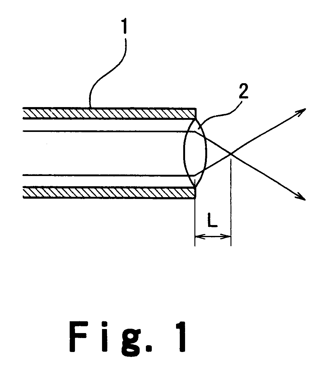
When the focal length L is too long, comparatively condensed beam may be emitted following trepanation of the crystalline lens, accordingly, too high irradiation amount of energy per unit area on the tissues behind the crystalline lens may be resulted so that these tissues may be damaged.

Method used


Image

  • Method of crystalline lens replacement
  • Method of crystalline lens replacement
  • Method of crystalline lens replacement

Examples


example 1

[Example 1]

Fifteen parts by weight of polyvinyl alcohol (PVA405; Kuraray Co., Ltd.; viscosity average polymerization degree: 500; saponification degree: 82 mol %) used as a hydrophilic polymer was dissolved in 85 parts by weight of saline (Otsuka Pharmaceutical Co., Ltd.) to prepare a liquid injectable composition to be refilled directly into the lens capsule. The injectable composition was 200 cP in viscosity, 1.358 in index of refraction, and 99% in visible light transmittance. This injectable composition was sealed into an injection cartridge, which was subjected to autoclave sterilization.

A small hole of about 1 mm in diameter was formed penetrating through the lens capsule of a rabbit with a cystotome hand piece shown in FIG. 3. Next, the lens substance was removed almost completely from the lens capsule through the hole by means of phacoemulsification. A 27-gauge needle was applied through the closure formed in accordance with Manufacturing Example 2. The tip of the closure wa...

example 2

[Example 2]

Forty parts by weight of poly(N-vinyl-2-pyrrolidone) (K-15; Gokyo Trading Co., Ltd.; average molecular weight: 10,000) used as a hydrophilic polymer was dissolved in 60 parts by weight of Opeguard MA.RTM. (Senju Pharmaceutical Co., Ltd.) to prepare a liquid injectable composition to be refilled directly into the lens capsule. The injectable composition was 370 cP in viscosity, 1.410 in index of refraction, and 87% in visible light transmittance. This injectable composition was sealed into an injection cartridge, which was subjected to autoclave sterilization.

A small hole of about 1 mm in diameter was formed penetrating through the lens capsule of a rabbit with a light guide having therein an optical fiber bundle of 1 mm in diameter. The lens capsule had previously been stained with an aqueous solution of indocyanine green (Daiichi Pharmaceutical Co., Ltd.; Diagnogreen.RTM. Injection) that optimizes laser energy absorption at a certain wavelength. A semiconductor laser wit...

example 3

[Example 3]

Sixty parts by weight of polyethylene glycol (PEG 1000; Wako Co.; average molecular weight: 1,000) used as a hydrophilic polymer was dissolved in 40 parts by weight of purified watei (Otsuka Pharmaceutical Co., Ltd.) to prepare a liquid injectable composition to be refilled directly into the lens capsule. The injectable composition was 440 cP in viscosity, 1.442 in index of refraction, and 97% in visible light transmittance. This injectable composition was sealed into an injection cartridge, which was subjected to autoclave sterilization.

The procedure in Example 1 was repeated to form a small hole penetrating through the lens capsule of a rabbit. A 21-gauge needle was applied in the hole closure formed according to the procedure in Manufacturing Example 5. The tip of the closure was inserted into the hole. Most of the vitreous body of the rabbit was aspirated. Then, the above-mentioned injectable composition was refilled through the same needle until the lens capsule rega...


PUM

PropertyMeasurementUnit
viscosityaaaaaaaaaa
visible light transmittanceaaaaaaaaaa
focal lengthaaaaaaaaaa

Abstract

A method of crystalline lens replacement for eyes comprises the steps of forming a small hole that penetrates through the lens capsule, removing a part of the crystalline lens substance through the hole, refilling the lens capsule by injecting a composition comprising a hydrophilic polymer directly into the lens capsule, and closing the hole. The method of crystalline lens replacement may be performed on animals or humans. Furthermore, the method of crystalline lens replacement may be performed on a patient suffering from cataract, where the opaque crystalline lens substance in the lens capsule is removed.

Description

The present invention relates to a method of crystalline lens replacement. More particularly, the present invention relates to a method of crystalline lens replacement for restoring optical properties, such as clarity and refraction, of the lens suffering from defects (e.g., cloudiness, complete opacification or loss of transparency) due to cataracts or other diseases, while keeping the ability of the normal lens to accommodate resulting from the relaxation and contraction of the ciliary muscle.DESCRIPTION OF THE PRIOR ARTCataract is a disease involving partial or complete opacity in / on the lens or capsule of the eye(s), which could result in significant loss of eyesight or even blindness. Cataracts can be classified to congenital or acquired, and known acquired cataracts include senile (age-related), diabetic and traumatic cataracts as well as other types thereof that may develop upon exposure to energy such as ultraviolet or nuclear radiation. Among these, senile cataracts are one...

Claims


Application Information

Patent Timeline
Patent Type & Authority Patents(United States)
IPC IPC(8): A61F9/00A61F9/007A61F2/14A61B18/20A61L27/00
CPCA61F9/0017A61F9/00736
Inventor SAISHIN, MOTOSUGUTSUKAMOTO, MITSUOYAMAUCHI, AIZO
Owner SAISHIN MOTOTSUGU
Learn More