Fully-coupled vehicle positioning method and system thereof

a fully-coupled vehicle and positioning method technology, applied in direction finders using radio waves, navigation instruments, instruments, etc., can solve the problems of range error (ure), measurement error not only affecting pseudorange measurements but phase measurements, and error not only affecting pseudorange measurements, etc., to improve the accuracy of receiver position and velocity, improve the performance of gps/ins, and accurately determine the receiver position and velocity

Inactive Publication Date: 2002-07-23
AMERICAN GNC
View PDF5 Cites 175 Cited by
  • Summary
  • Abstract
  • Description
  • Claims
  • Application Information

AI Technical Summary

Benefits of technology

An objective of the present invention is to use the velocity and acceleration from an inertial navigation processor, which are corrected by a Kalman filter, as the aiding of the code and carrier phase tracking of the GPS satellite signals so as to enhance the performance of the GPS / INS, even in heavy jamming and high dynamic environments, and to improve the accuracy of the receiver position and velocity by using differential GPS. To accurately determine the receiver position and velocity at the centimeter level, the GPS phase measurements will be used and the differential GPS will be employed. In this invention, a new process (OTF (on-the-fly) technique) is disclosed to resolve the integer ambiguities on the fly and estimate the receiver position in real time. The results of GPS estimates will increase the accuracy of the inertial navigation system and therefore enhance the capability of the GPS tracking loop.
Another objective of the present invention is to provide a real-time integrated vehicle positioning method, which uses the GPS raw phase measurements to update the inertial navigation system and aids the GPS tracking loop by the accurate output of the inertial navigation system so as to satisfy the requirements of, such as, low cost, high accuracy, continuous output, high degree of resistance to jamming, and high dynamics, and to overcome the disadvantages of the existing techniques.

Problems solved by technology

These errors not only affect pseudorange measurements but phase measurements.
The most obvious difference between both measurements is the measurement error.
The Global Positioning System, GPS, contains a number of error sources: the signal propagation errors, satellites errors, and the selective availability.
The user range error (URE) is the resultant ranging error along the line-of-sight between the user and the global positioning system satellite.
Global positioning system errors tend to be relatively constant (on average) over time, thus giving the global positioning system long-term error stability.
However, the signals of the global positioning system may be intentionally or unintentionally jammed or spoofed, or the global positioning system (GPS) receiver antenna may be obscured during vehicle attitude maneuvering, and the global positioning system signals may be lost when the signal-to-noise ratio is low and the vehicle is undergoing highly dynamic maneuvers.
In addition to the unavoidable errors (such as ionospheric delay, tropospheric delay, clock biases, and measurement errors) and the intentional error (such as SA), the GPS measurements (pseudorange and phase) may also be affected by the environment surrounding a GPS user antenna.
For a highly dynamic vehicle, the onboard GPS receiver may lose the lock of a GPS signal because the signal-to-noise ratio (SNR) is low or the GPS signal is blocked by the body of its own vehicle.
Also, with the availability of modem gyros and accelerometers, the strapdown inertial navigation systems become the predominant mechanization due to their low cost and reliability.
However, an inertial navigation system is expensive and is degraded with drift in output (position and velocity) over an extended period of time.
It means that the position and velocity errors increase with time.
This error propagation characteristic is primarily caused by, such as, gyro drift, accelerometer bias, misalignment, gravity disturbance, initial position and velocity errors, and scale factor errors.
Under the requirements, such as low cost, high accuracy, continuous output, high degree of resistance to jamming, and high dynamics, the stand-alone INS and stand-alone GPS have difficulties to perform properly.
1. In the conventional global positioning system and inertial navigation system integration approaches, only position and velocity from the output of the GPS receiver or the GPS raw pseudorange and delta range measurements are used. However, the GPS raw phase measurements haven't been used for an integration solution, although the phase measurements are accurate to a few millimeters in contrast to 30 centimeters for the P code pseudorange or 3 meters for the C / A code pseudorange in the presence of measurement noise.
2. There is a significant impediment to the aiding of the global positioning system signal tracking loops with an inertial navigation system. It is that the aiding causes the potential instability of the conventional global positioning system and inertial navigation integration system because of a positive feedback signal loop in the integrated global positioning and inertial system. As a result, the degradation in accuracy of the inertial aiding data increases the signal tracking errors. And, the increased tracking errors are fed back into the inertial system. This may cause further degradation of the inertial system because the measurements may severely affect the Kalman filter, which is well tuned for a low accuracy inertial navigation system.
3. The inertial sensors in the conventional tightly-coupled GPS and inertial integration system can not provide the high accuracy in velocity. Therefore, the aiding of a carrier phase tracking loop can not execute properly due to the need for high accuracy of the external input velocity.

Method used


Image

  • Fully-coupled vehicle positioning method and system thereof
  • Fully-coupled vehicle positioning method and system thereof
  • Fully-coupled vehicle positioning method and system thereof

Examples


Embodiment Construction

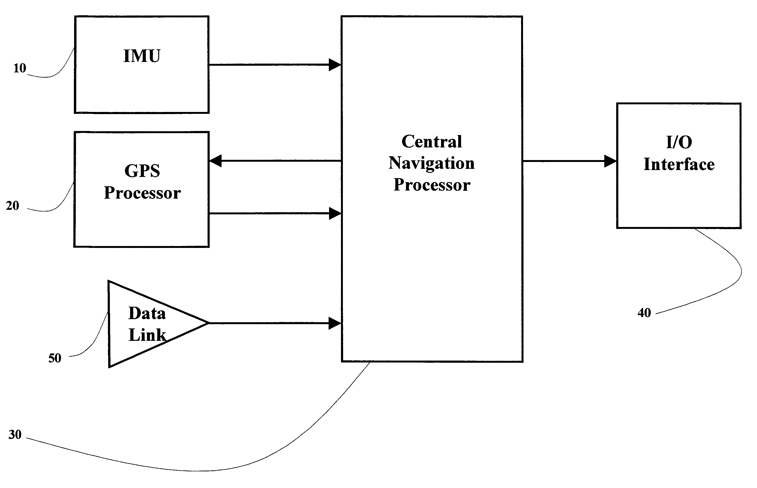
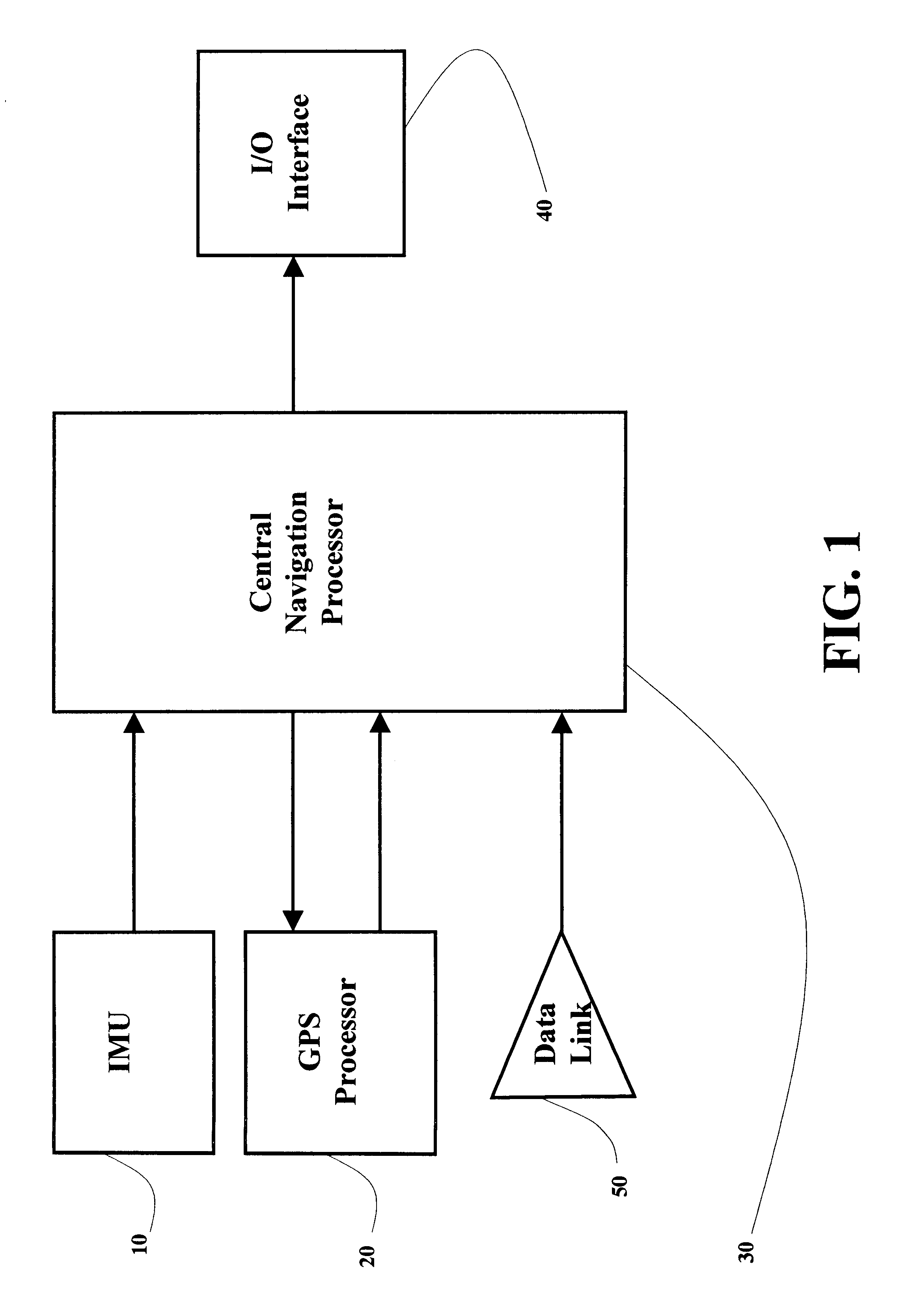
The improved fully-coupled GPS / IMU vehicle positioning system with differential GPS of the present invention, as shown in FIG. 1, comprises an IMU (inertial measurement unit) 10 and a GPS (global positioning system) processor 20 which are connected to a central navigation processor 30. The navigation solution is output to an I / O (input / output) interface 40. To perform differential GPS, a data link 50, which is also connected to the central navigation processor 30, is used to receive the position, velocity, and raw measurements (pseudorange and phase) from the reference site. The central navigation processor 30 is responsible for all data processing tasks.

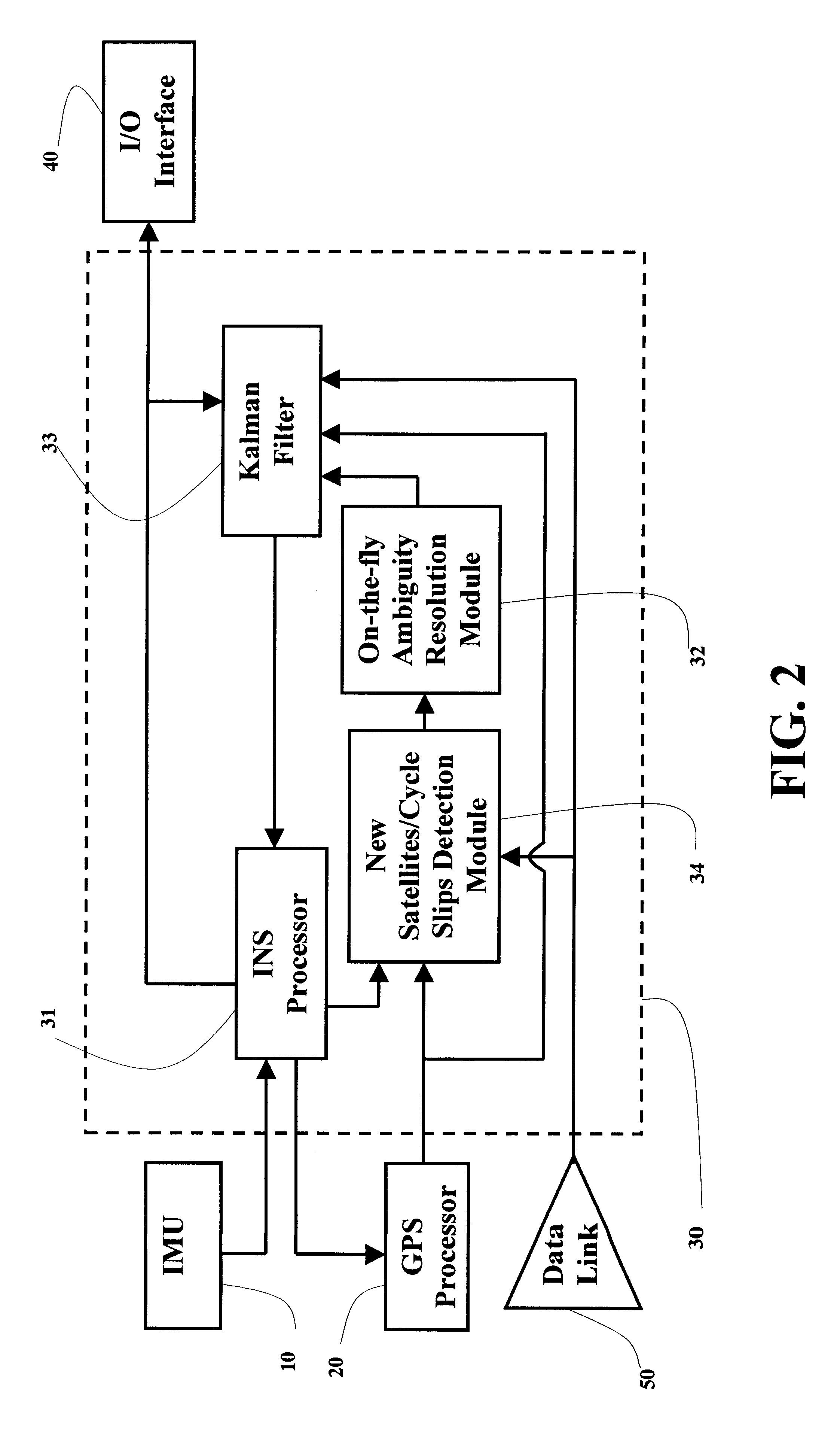
Referring to FIG. 1 and FIG. 2, the improved fully-coupled global positioning system / inertial measurement unit (GPS / IMU) vehicle positioning process with differential GPS of the present invention comprises the following steps.

a) Receive GPS rover measurements (including pseudorange, carrier phase, and Doppler shift) from the GPS pro...


PUM


Abstract

A fully-coupled vehicle positioning method and system with differential GPS substantially solves problems encountered in either the global positioning system-only or the inertial novigation system-only, such as loss of global positioning satellite signal, sensitivity to jamming and spoofing, and an inertial solution's drift over time, in which the velocity and acceleration from an inertial navigation processor of the integrated GPS / INS system are used to aid the code and carrier phase tracking of the global positioning system satellite signals, so as to enhance the performance of the global positioning and inertial integration system, even in heavy jamming and high dynamic environments. To improve the accuracy of the integrated GPS / INS navigation system, phase measurements are used and the idea of the differential GPS is employed. A master-slave relative positioning scheme is invented and is effective for high accuracy formation driving and flight.

Description

FIELD OF THE PRESENT INVENTIONThe present invention relates generally to a global positioning system and inertial measurement unit (GPS / IMU) integrated positioning and navigation method and system, and more particularly to an improved fully-coupled integration method and system of the global positioning system (GPS) receiver and the inertial measurement unit (IMU), which allows the mutual aiding operation of the GPS receiver and the inertial navigation system (INS) at an advanced level with features of inertial aiding global positioning system satellite signal tracking, fuzzy logic for attitude determination, master-slave relative positioning, robust attitude determination, and on-the-fly resolution of GPS carrier phase integer ambiguities and real-time positioning in the differential GPS mode.BACKGROUND OF THE PRESENT INVENTIONThe GPS user equipment, which comprises an antenna, a signal processing unit, and associated electronics and displays, receives the signals from the GPS sate...

Claims


Application Information

Patent Timeline
Patent Type & Authority Patents(United States)
IPC IPC(8): G01C21/10G01C21/16G01S5/14G01S19/48
CPCG01C21/165G01S19/26G01S19/28G01S19/44G01S19/55
Inventor LIN, CHING-FANG
Owner AMERICAN GNC
Why Eureka
Try Eureka