Differential device and method of manufacturing the device

a technology of differential devices and manufacturing methods, applied in the direction of differential gearings, mechanical devices, gearings, etc., can solve the problems of loss of driving force, failure to escape, loss of driving force for running on a curve at a high speed,

Inactive Publication Date: 2002-10-15
HITACHI METALS LTD
View PDF13 Cites 26 Cited by
  • Summary
  • Abstract
  • Description
  • Claims
  • Application Information

AI Technical Summary

Problems solved by technology

However, when one of the driving wheels is trapped in snow, sand, etc. or falls in a ditch, one wheel runs idle by differential rotation, resulting in total loss of a driving force, etc., which leads to failure to escape from the trapping.
In the case of turning a curve, a wheel runs idle when a load applied to wheels on the radial inside at turn extremely decreases, thereby losing a driving force for running on a curve at a high speed.
Accordingly, it is disadvantageous in combination with an apparatus required to have independence from the rotation of each wheel, such as an anti-lock brake system.
However, because an initial resistance is given by a viscous liquid, it still suffers from the disadvantage that the driving wheels are constraining each other.
When one of the driving wheels runs idle, a sliding friction force is generated between the outer surfaces of the disc plates and thrust washers by a thrust force generated in the disc plates connected to the driving wheels, thereby obtaining differential limitation effects.
(1) With respect to durability, metal peeling takes place on the inner surfaces of the winding continuous grooves of the disc plates 3, 4, and the peeling always occurs in any one of the regions a, e, If, g and h shown in FIG. 21. Also, there is a tendency that the metal peeling occurs on the side above the centerline 38 in the regions a, f and h, and on the side below the centerline 38 in the regions e and g in this figure.
(2) With respect to torque characteristics, a torque on the side of the disc plates 3, 4 varies periodically, though a constant torque is applied to the ball holder 5, and its variation period is equal to a half of the period at which the ball 6 moves along the unit region (period at which a ball moves radially back and forth in one cycle in the guide hole). This variation period is constituted by some smaller variation periods.
Because there are ten balls in total, these forces are in an unstable state that cannot be dynamically determined only from the balance of moments of forces.
However, when a carburizing treatment is conducted to the winding continuous groove, edge portions of the winding continuous groove have a high-carbon content, resulting in embrittlement despite of increase in hardness.
As a result, when a ball is brought into contact with an edge of the winding continuous groove, cracking may take place, resulting in the deterioration of durability of the differential apparatus and unstable torque transmission.
In addition, the above production method has too many steps, suffering from a problem of high production cost.
With respect to rough working and finish working of the winding continuous groove 31 by the ball end mill 16, a large cutting resistance is applied to a tip end 16a of the ball end mill 16, because a cutting speed is zero at the tip end 16a of the ball end mill 16, thereby posing a problem that it is difficult to form the shape and locus of the winding continuous groove at a high precision.
This leads to a long working time period.
Also, because the special end mill is expensive and needs regrinding, it is more expensive than usual tools.
Accordingly, there is a problem of high production cost of the differential apparatus.
However, the special end mill is not only expensive but also more costly in regrinding than usual tools, fewer in the maximum number of regrinding than usual tools, suffering from a short service life.
Further, because it is difficult to work 10 or so guide holes simultaneously on the ball holder 5, it suffers from a long working time, thereby needing a method of easily working the guide holes.
If the balls 6 slidably move without rotation under such a high load (causing slipping), the inner walls of the guide holes 51 are likely to be damaged.
However, when a high contact stress

Method used


Image

  • Differential device and method of manufacturing the device
  • Differential device and method of manufacturing the device
  • Differential device and method of manufacturing the device

Examples


example 1

Comparative Example 1

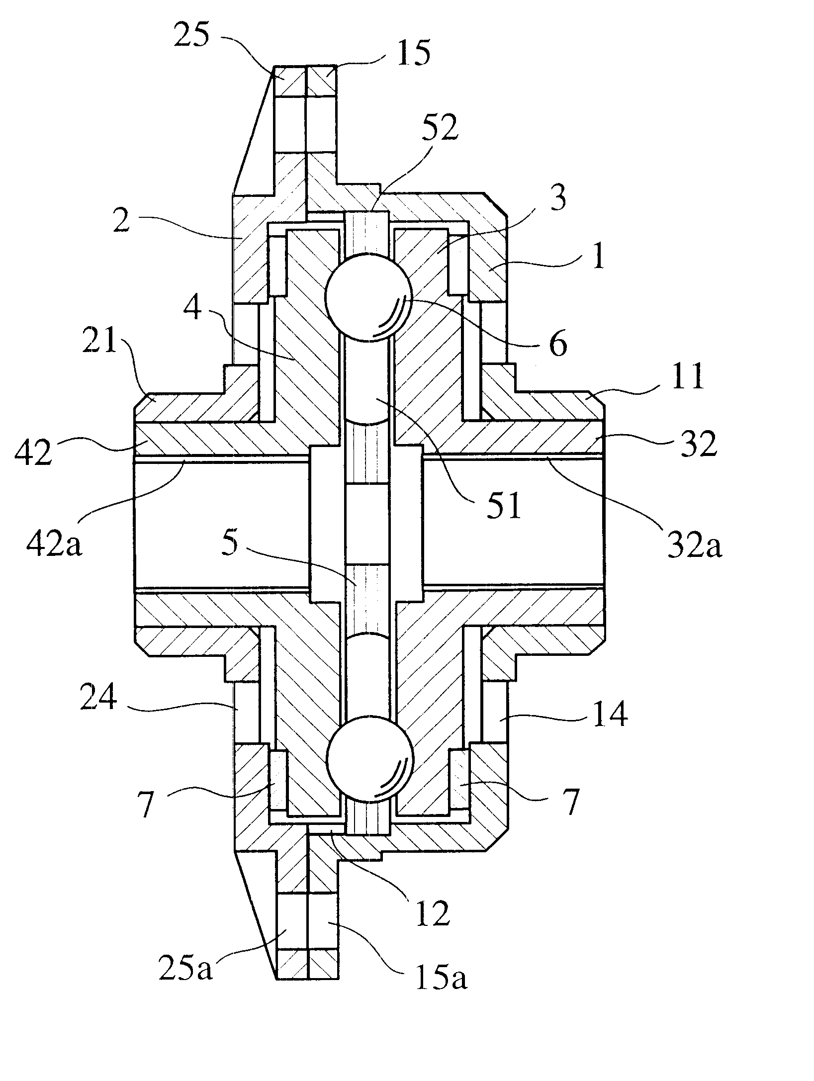
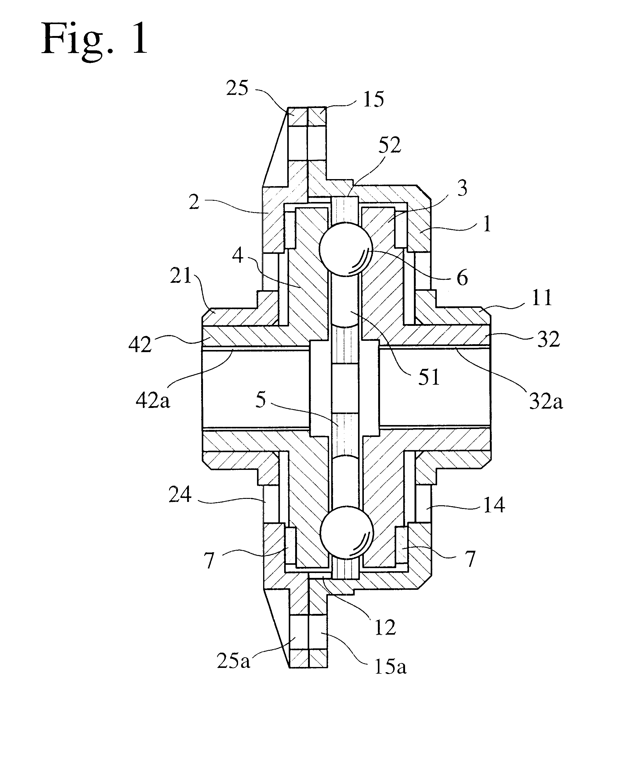
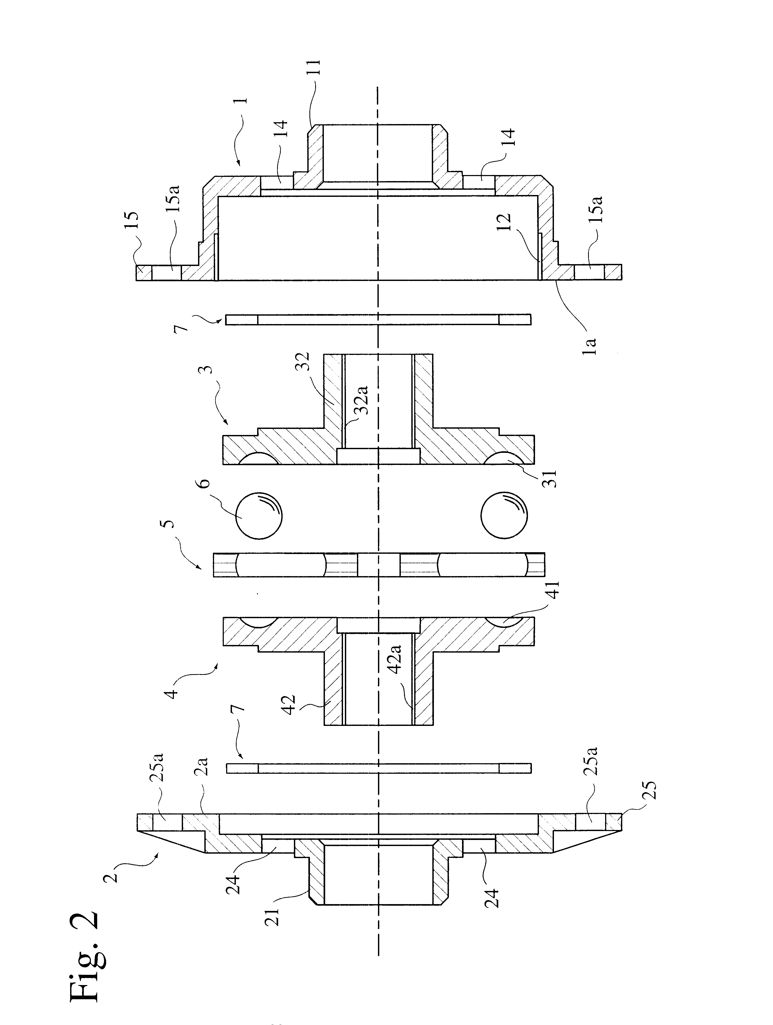
With the differential apparatus shown in FIGS. 1-3, a lubrication durability test was carried out. Each steel ball made of JIS SUJ2 had a diameter of 16.00 mm, and a steel-made ball holder 5 having 10 guide holes 51 was 90 mm in diameter and 6 mm in thickness. Each guide hole 51 had a width of 16.0 mm. The disc plates 3, 4, the ball holder 5 and the balls 6 were subjected to a chemical treatment by immersion in a chemical treatment bath containing a phosphate chemical treatment agent (tradename: Ferrycoat 7, available from Japan Parkerizing, Co., Ltd.) at 80.degree. C. for 10 minutes. The chemical treatment coating layer formed on each part had an average thickness of 5 .mu.m.

Each part formed with the chemical treatment coating layer was assembled to a differential apparatus of EXAMPLE 1, and the same differential apparatus as in EXAMPLE 1 except for forming no chemical treatment coating layer was identified as COMPARATIVE EXAMPLE 1. Operation tests were conduct...

example 2

The inner surfaces of the guide holes 51 of the ball holder 5, the surfaces of the balls 6, and the surfaces of the guide grooves 31, 41 of the disc plates 3, 4, which were formed with a chemical treatment coating layer as in EXAMPLE 1. were sprayed with a solid lubricant treatment solution of a molybdenum disulfide-containing, resin-based coating composition (tradename: HMB-2, available from Japan Parkerizing, Co., Ltd.) diluted with an organic solvent, dried at room temperature, and then baked at 200.degree. C. for 60 minutes to form a solid lubricating layer. The solid lubricating layer formed on the chemical treatment coating layer of the guide holes 51 had an average thickness of 10 .mu.m, and the solid lubricating layer formed on the chemical treatment coating layer of the ball 6 had an average thickness of 5 .mu.m. Also, the solid lubricating layer formed on the chemical treatment coating layer on the guide grooves 31, 41 of the disc plates 3, 4 had an average thickness of 10...

examples 3 , 4

EXAMPLES 3, 4

With the rolling-forming apparatus shown in FIG. 41, a winding continuous groove of a disc plate for a differential apparatus was worked. A disc plate die 401 used was made of alloyed tool steel (JIS SKS3) having a hardness of HRC 60. Rolling-forming balls 9 each having a diameter of 16.00 mm were made of high-carbon chromium bearing steel (JIS SUJ3) having a hardness of HRC 62 or more. The ball holder 5 having a diameter of 44 mm and a thickness of 5.5 mm was made of chromium-vanadium steel (JIS SUP10) having a hardness of HRB 400.

First, the disc plate precursor 402 was cut to form a winding continuous groove 421 having a U-shaped cross section, such that a rolling-forming margin was about 0.1 mm (EXAMPLE 3), and 0.2 mm (EXAMPLE 4), respectively. Incidentally, portions not contributing to the transmission of force may be provided with recesses or notches. The primarily worked disc plate precursor 402 was assembled as shown in FIG. 41, disposed in a metal case and then ...


PUM


Abstract

The differential apparatus comprises (a) a casing rotated by a driving force from outside; (b) a pair of opposing disc plates coaxially disposed in the casing, an opposing surface of each disc plate being formed with a circumferentially continuous groove winding such that a radial position changes at a constant period; (c) a plurality of balls rolling in opposing winding continuous grooves of both disc plates; and (d) a ball holder rotating integrally with the casing and having a plurality of radially extending guide holes, each guide hole movably receiving each ball, wherein the winding continuous groove of each disc plate circumferentially continuously has first guide regions each extending from a radially outer position to a radially inner position of each disc plate and second guide regions each extending from a radially inner position to a radially outer position, inflected regions each connecting each first guide region and each second guide region being larger in width and/or depth than the first guide regions and the second guide regions, whereby a contact stress between the balls and the winding continuous groove is decreased in the inflected regions.

Description

The present invention relates to a differential apparatus capable of achieving difference in rotation between right and left driving wheels or between front and rear drive shafts of automobiles, and capable of increasing a driving force by generating a differential-limiting torque when one of driving wheels or drive shafts is rotating idle, and a method for producing such a differential apparatus, particularly to a differential apparatus having good durability and a stable differential-limiting torque and a method for producing such a differential apparatus.PRIOR ARTA differential apparatus of an automobile is an apparatus enabling difference in rotation between right and left driving wheels or between front and rear driving wheels when the automobile turns a curve (in the case of a four-wheel driving vehicle). Widely used as a differential apparatus having such a function for automobiles is conventionally a differential apparatus comprising a pinion gear between a pair of bevel gea...

Claims


Application Information

Patent Timeline
IPC IPC(8): F16H15/40F16H48/00F16H48/12F16H25/06F16H15/04F16H25/00F16H57/02
CPCF16H48/147F16H48/12Y10T74/19005F16H48/40
Inventor ITO, YOSHITAKAOHUCHI, MAKOTOHARA, MASANORINAKAMURA, AKITOSHIMARUYAMA, NAOKIWATANABE, NAOTOMIKAMI, AKIRAYAMADA, SHUUJIKURAKAKE, KAZUYUKI
Owner HITACHI METALS LTD
Why Eureka
Try Eureka