Process and apparatus for making oriented crystal layers

a technology of crystal layers and crystal layers, applied in the direction of crystal growth process, vacuum evaporation coating, coating, etc., can solve the problem that materials having this property are not useful as seed layers for electronic materials

Inactive Publication Date: 2002-11-26
LOS ALAMOS NATIONAL SECURITY
View PDF9 Cites 19 Cited by
  • Summary
  • Abstract
  • Description
  • Claims
  • Application Information

AI Technical Summary

Problems solved by technology

While this property is useful for catalysis, hardness or corrosion properties, materials having this property are not useful as seed layers for electronic materials.

Method used


Image

  • Process and apparatus for making oriented crystal layers
  • Process and apparatus for making oriented crystal layers
  • Process and apparatus for making oriented crystal layers

Examples


example

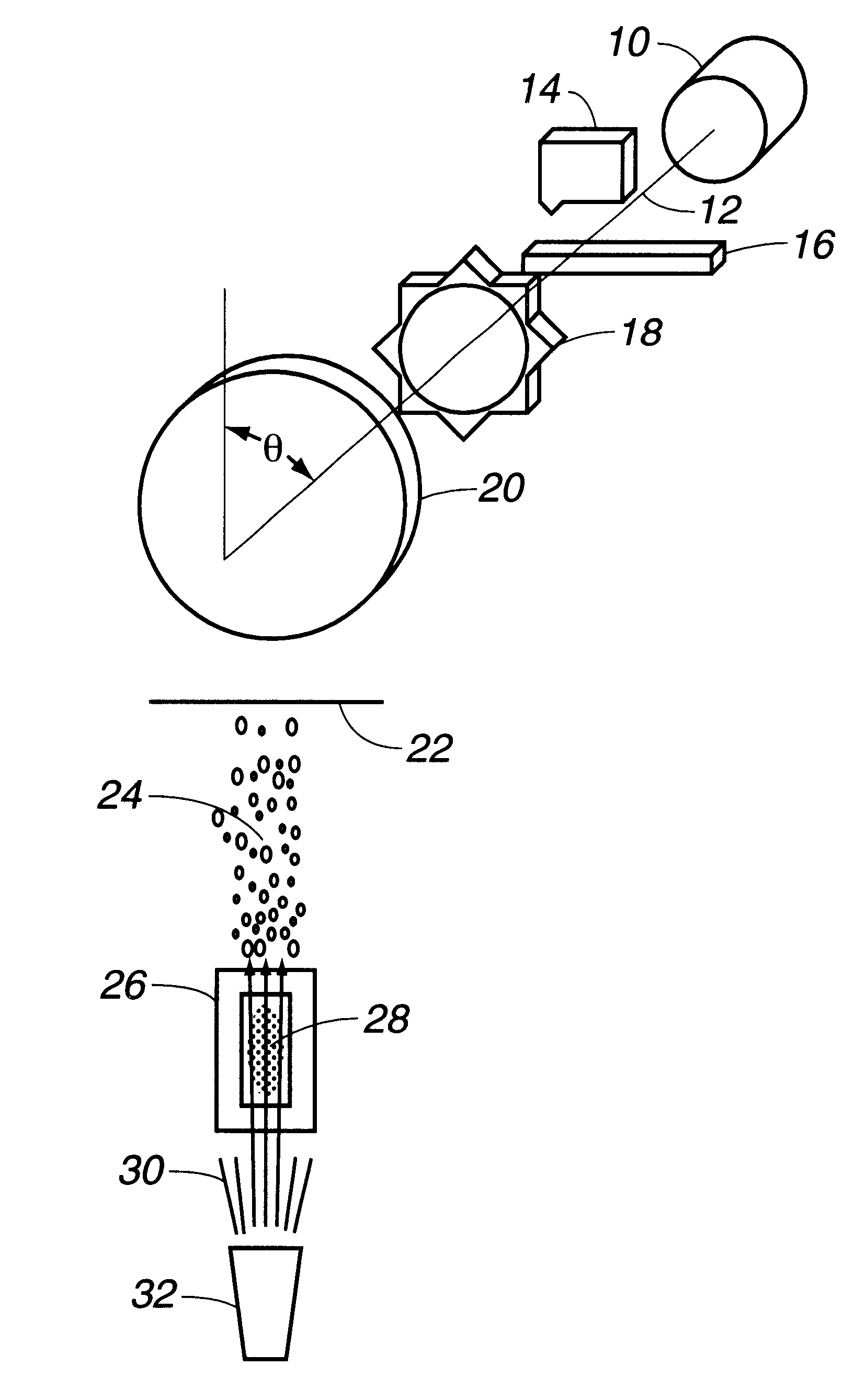
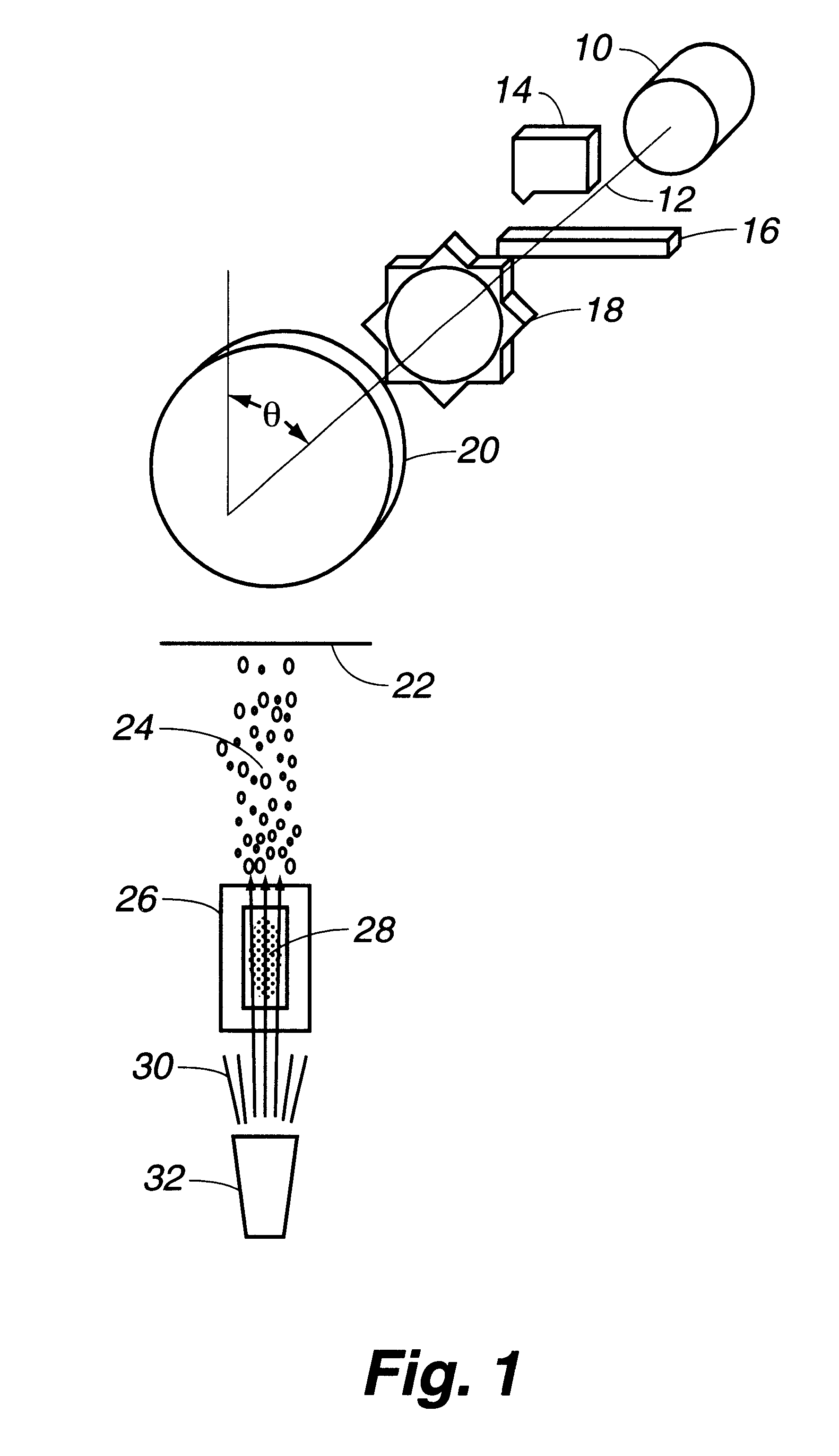
To demonstrate operability of the invention, an invention device was set up with a DC vacuum motor arranged to rotate a substrate holder over a flow through ion beam source in a manner substantially similar to that shown in the schematic of FIG. 1.

The substrate was placed over the ion beam source and magnesium oxide feedstock material was evaporated through the ion beam source to produce an oriented film.

A glass microscope slide abut 1".times.3".times.0.05" was used as a substrate. Glass was selected as a substrate because the amorphous glass, lacking any crystal structure, would not seed, assist or otherwise influence the crystal formation or orientation.

The substrate was placed on the substrate holder which was attached to a shaft of a DC vacuum motor.

The substrate was inclined at an angle of about 28.degree. relative to the beam from the ion beam source.

The flow through ion beam source was operated in the manner described in U.S. Pat. No. 5,601,654 using oxygen as the plasma gas....


PUM

PropertyMeasurementUnit
angleaaaaaaaaaa
anglesaaaaaaaaaa
angleaaaaaaaaaa

Abstract

Thin films of single crystal-like materials are made by using flow-through ion beam deposition during specific substrate rotation around an axis in a clocking action. The substrate is quickly rotated to a selected deposition position, paused in the deposition position for ionized material to be deposited, then quickly rotated to the next selected deposition position. The clocking motion can be achieved by use of a lobed cam on the spindle with which the substrate is rotated or by stopping and starting a stepper motor at long and short intervals. Other symmetries can be programmed into the process, allowing virtually any oriented inorganic crystal to be grown on the substrate surface.

Description

This invention relates to deposition of inorganic oriented crystal layers using ion beam deposition technology.Crystallites having the same orientation with respect to the plane of the substrate but twisted relative to each other have been produced. While this property is useful for catalysis, hardness or corrosion properties, materials having this property are not useful as seed layers for electronic materials. Electronic materials must be as defect free as possible, and they need to be single crystals or single crystal-like to achieve optimum electrical performance. These materials have been produced using molecular beam epitaxy, which requires the use of a single crystal surface on which to grow the electronic material and multiple sources. Therefore, there is a need for simpler, faster methods of production that can build oriented crystal layers on substrates other than single-crystal substrates, particularly for uses such as high temperature material applications.It is an objec...

Claims


Application Information

Patent Timeline
Patent Type & Authority Patents(United States)
IPC IPC(8): C30B23/02
CPCC30B23/02Y10T117/1004
Inventor SPRINGER, ROBERT W.
Owner LOS ALAMOS NATIONAL SECURITY
Why Eureka
Try Eureka