Multi heating zone apparatus and process for making core/clad glass fibers

a technology of core/clad glass fiber and heating zone, which is applied in the field of process and apparatus for fabricating core/clad glass fiber, can solve the problems of not being thermally stable, unable to soluble rare earth elements in most stable chalcogenide glasses, and having a tendency to crystallize, and achieves the effect of not adding additional loss, increasing fiber loss, and negative loss

Inactive Publication Date: 2003-03-04
THE UNITED STATES OF AMERICA AS REPRESENTED BY THE SECRETARY OF THE NAVY
View PDF8 Cites 11 Cited by
  • Summary
  • Abstract
  • Description
  • Claims
  • Application Information

AI Technical Summary

Benefits of technology

Gallium and rare earth elements typically destabilize glass leading to crystallization and increased loss in the fiber. The obvious approach is to avoid the use of gallium and rare earth elements in the glass and this is done at times. However, some applications require the presence of gallium and / or rare earth elements, or the presence of gallium and / or rare earth elements in the glass is desired for some reason. In instances when a rare earth element and / or gallium is present, fabrication of the glass containing a rare earth or gallium must be carried out in a way that avoids exposure of the glass to temperature that results in crystallization so as not to add additional loss. This can be achieved using the apparatus and / or process of this invention where the core glass temperature is well below the crystallization temperature .
It should be understood that it is the core in a core / clad fiber that is doped with at least one rare earth element. Insolubility of rare earth elements in some glasses is well recognized as its cause of crystallization and consequent negative effect on loss. Therefore, if the core glass contains gallium and / or rare earth element(s), the core glass should be kept from high temperature which can cause crystallization therein in addition to the insolubilization problem.
Before proceeding to the apparatus and process, FIG. 1 demonstrates typical relative disposition of the various temperatures that the core and / or clad glasses may experience. FIG. 1 starts at the left hand portion of the plot where room temperature (RT) is shown, followed in ascending order by glass transition temperature (T.sub.g), fiber draw temperature (T.sub.d), crystallization temperature (T.sub.x), and liquidus temperature (T.sub.1), or RT<T.sub.g <T.sub.d <T.sub.x <T.sub.1-. At draw temperature T.sub.d, glass is softened to the point of being in a flowing condition but well below the crystallization temperature T.sub.x and the liquidus temperature T.sub.1. So, by carrying the operation below the crystallization temperature T.sub.x, formation of crystals and occlusions, including bubbles, can be avoided and the glass can have a lower loss.

Problems solved by technology

Unfortunately, rare earth elements are not soluble in most stable chalcogenide glasses, such as arsenic sulfide (As.sub.40 S.sub.60) or arsenic selenide (As.sub.40 Se.sub.60).
Other chalcogenide glasses, such as gallium-containing sulfide or selenide glasses that can dissolve sufficient amount of rare earth elements, are not thermally stable and have a tendency to crystallize during the fiber drawing process.
Using that technique for fabricating optical fibers from less thermally stable chalcogenide glasses, such as GeGaAsS or GeGaAsSe, especially when these glasses are doped with rare earth elements, is not possible because they will crystallize during the slow cooling process from their melting temperature to the drawing temperature.

Method used


Image

  • Multi heating zone apparatus and process for making core/clad glass fibers
  • Multi heating zone apparatus and process for making core/clad glass fibers
  • Multi heating zone apparatus and process for making core/clad glass fibers

Examples


example 2

In order to fabricate single-mode fibers, the fiber drawing conditions of Ex. 1 were changed as follows: the pressure above the core glass was reduced to one inch of water, the pressure above the cladding glass was raised to two psi, and the drawing speed increased to 15 m / min. The resulting fiber had a core diameter of 7 microns and overall diameter of 80 microns.

example 3

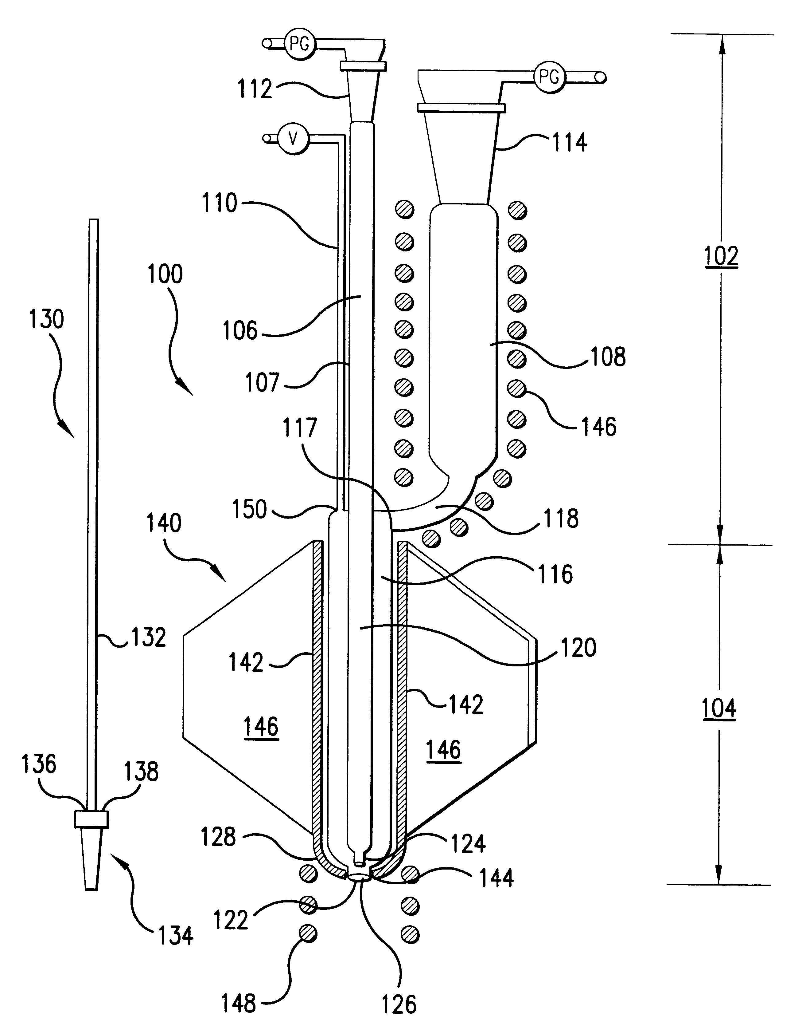
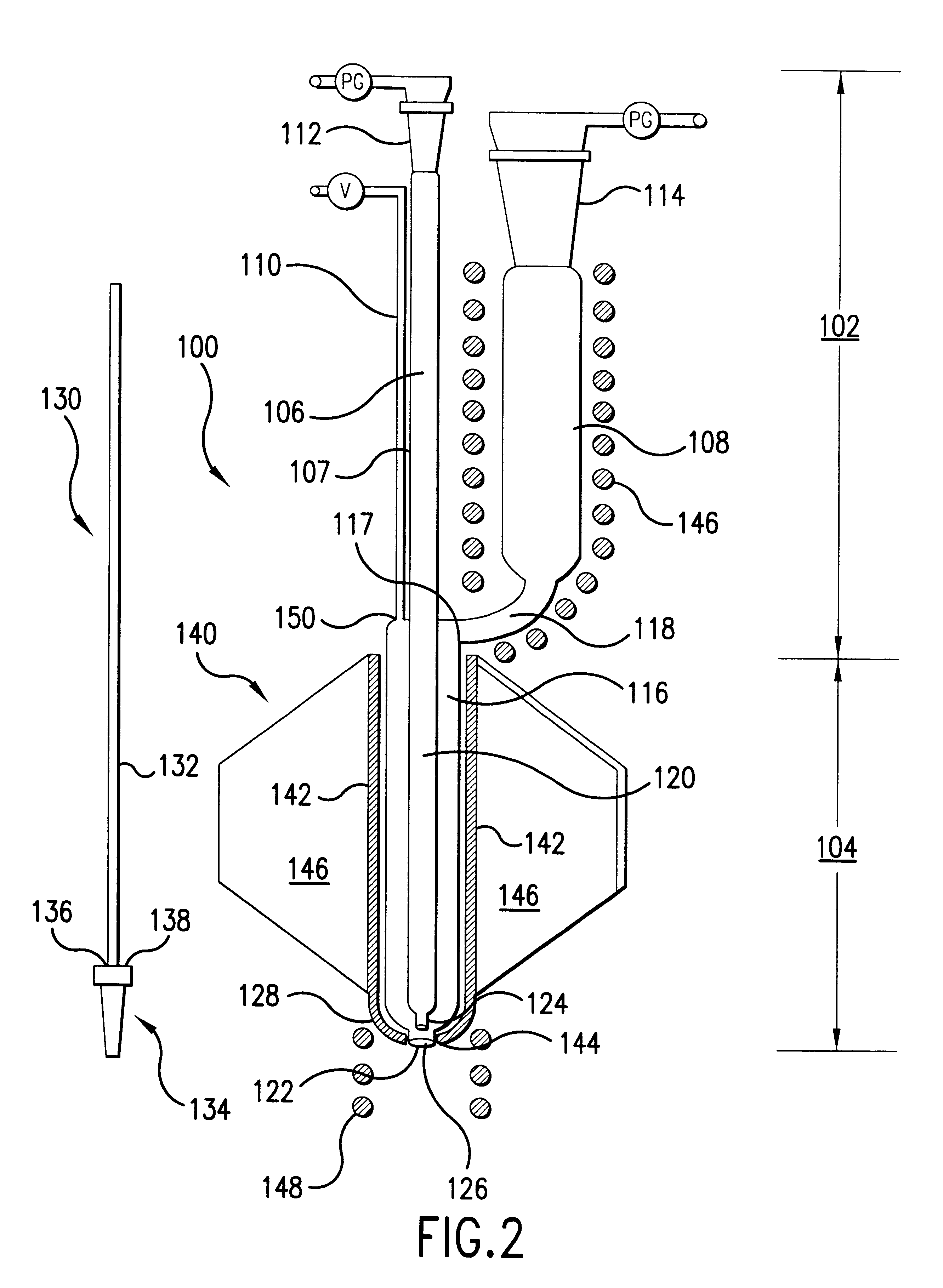
Procedure of Ex. 1 was followed in fabricating single mode glass fiber of core diameter of 4 microns and overall diameter of in excess 125 microns. Fabrication of the single mode fiber of core diameter of 4 microns was made possible by a modification to the apparatus, as shown in FIG. 4, which involved replacing plug 130 with a much shorter plug to block orifices 122, 126 and suspending the core glass rod from the top by means of a wire secured to a notch in the core glass rod. The wire was threaded through a cap disposed at the upper extremity of the center tube.


PUM

PropertyMeasurementUnit
diameteraaaaaaaaaa
thickaaaaaaaaaa
softening temperatureaaaaaaaaaa

Abstract

This invention pertains to apparatus and process for making core/clad glass fibers. The apparatus includes a central tube or receptacle connected at the top to a pressure controller and terminating in a reduced section; a side tube or receptacle positioned at about the level of the upper portion of the central tube; an outer tube or receptacle disposed around the bottom portion of the central tube terminating in a smaller section which is concentric with and spaced directly below the section of the central tube; a side arm connecting the side tube and the outer tube; and furnaces around the side, outer, and the reduced sections of the central and the outer tubes. The process includes the steps of disposing a solid core glass rod at a point removed from hot temperature that can cause crystallization in the core glass rod, disposing a solid clad glass rod at a point removed from the core glass rod, softening to the flowing condition the solid clad glass rod, transferring the softened clad glass to a lower point, the softened clad glass having a central void therethrough, heating the softened clad glass above its crystallization temperature, cooling the softened clad glass to a draw temperature, transferring the solid core glass rod into the central void in the softened clad glass, softening to the flowing condition the solid core glass rod with the heat from the softened and cooled clad glass, and drawing the core/clad glass fiber by allowing the clad and core glasses to flow in the form of a fiber.

Description

1. Field of the InventionThis invention pertains to a multiple heating zone process and apparatus for fabricating core / clad optical glass fibers, particularly from thermally unstable glass.2. Description of Related ArtAlthough this discussion will focus on the chalcogenide glasses, it should be understood that this invention pertains to other glasses as well, including oxide and fluoride glasses, which are thermally unstable in that crystallization occurs during fiber fabrication thereof during cooling of the core to the draw temperature through the crystallization temperature.Silica glass has phonon energy of about 1100 cm.sup.-1, fluoride glass has phonon energy of about 560 cm.sup.-1, and chalcogenide glass has phonon energy of about 425 cm.sup.-1 and lower. It is chalcogenide glass that is often used to make glass fibers for infrared applications, due to its low phonon energy and its spectral range of 2-12 microns.Chalcogenide glasses and optical fibers made therefrom can transm...

Claims


Application Information

Patent Timeline
Patent Type & Authority Patents(United States)
IPC IPC(8): C03B37/023C03B37/02
CPCC03B37/023C03B2201/86C03C3/321C03C13/043
Inventor MOSSADEGH, REZACOLE, BRIANPUREZA, PABLOSANGHERA, JASBINDERBAYYA, SHYAMAGGARWAL, ISHWAR
Owner THE UNITED STATES OF AMERICA AS REPRESENTED BY THE SECRETARY OF THE NAVY
Why Eureka
Try Eureka