Multiwall polymeric microcapsules from hydrophilic polymers

a polymer and polymer technology, applied in the field of multi-wall polymeric microcapsules from hydrophilic polymers, can solve problems such as suspension or emulsion

Inactive Publication Date: 2003-03-04
BROWN UNIV RES FOUND INC
View PDF34 Cites 18 Cited by
  • Summary
  • Abstract
  • Description
  • Claims
  • Application Information

AI Technical Summary

Benefits of technology

The systems are grouped according to nonionic-, ionic- and salt-polymer interactions. The variables that must be controlled when preparing two-phase aqueous systems include: polymer concentration and molecular weight, ionic composition, temperature, time allowed for separation and interfacial tension. The interfacial tension is directly affected by the polymer concentration. As an example, the interfacial tension of the PEG-dextan system can vary from 0.0001 to 0.1 mN m.sup.-1 by increasing the concentration of the components.
It is critical to control the rate of solvent removal, as well as the parameters previously discussed, for one polymer solution to form a layer around a core of another polymer solution and to produce uniform layers. However, the effect of the rate of solvent removal on polymer layer formation may be used advantageously to modify the final product. For example, increasing the rate of solvent removal causes the formation of spheres of the first polymer within the second polymer layer. The inclusion of the spheres can be useful in forming "channels" of one polymer within the other. By increasing the rate of evaporation still further, no inner layer is formed and all of the first polymer is present in spherical form within the second polymer layer. Inclusion of the spheres may be useful in forming "channels" of a biodegradable polymer such as zein, bovine serum (BSA), human serum albumin (HSA), and PEG-PLGA within an outer layer of a non-degradable polymer such as polyethylene glycol (PEG).

Problems solved by technology

By selecting the appropriate solvents and polymers, the two solutions will not be soluble in each other and will result in a suspension or emulsion.

Method used


Image

  • Multiwall polymeric microcapsules from hydrophilic polymers
  • Multiwall polymeric microcapsules from hydrophilic polymers
  • Multiwall polymeric microcapsules from hydrophilic polymers

Examples


example 2

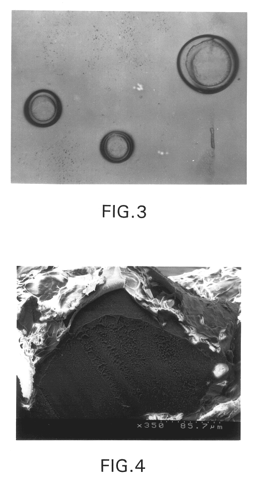
Microspheres Prepared from Agarose and Gelatin

A similar method to Example 1 was used with agarose and gelatin as the polymers, however, in this case, the differences in gelation temperatures induced phase separation. Separate solutions of 20% agarose (w / v) and 4% gelatin (w / v) were prepared and maintained at 50.degree. C. to keep the solutions in the liquid state. The solutions were mixed in equal volumes, dispersed by shaking and poured into 300 mL of mineral oil at 80.degree. C. The mixture was stirred until the emulsion droplets were of an appropriate size range, then the oil bath was rapidly cooled to 4.degree. C. The microspheres were collected by decanting the oil and were washed with ethanol. The spheres were analyzed with scanning electron microscopy (SEM) (FIG. 4). The inner core of these spheres consisted of agarose, which solidifies at 42.degree. C., while the outer core consisted of gelatin which solidifies at 4.degree. C.


PUM

PropertyMeasurementUnit
gelling temperatureaaaaaaaaaa

Abstract

Two or more hydrophilic polymers that are not soluble in each other at a particular concentration and temperature, but which have a positive spreading coefficient in solution, are used to form multi-layered polymeric microspheres. The multi-layer microspheres produced by the method are distinguished by extremely uniform dimensioned polymer layers and actual incorporation of a substance to be delivered into the polymer layers. In the preferred embodiment of the method, two polymers are dissolved in an aqueous solvent, the substance to be incorporated is dispersed or dissolved in the polymer solution, the mixture is suspended in an organic solvent or polymer / water mixture and stirred, and the solvent is slowly evaporated, creating microspheres with an inner core formed by one polymer and an outer layer formed by the second polymer.

Description

The present invention is a method for preparing multiwall polymer microspheres, particularly for use in controlled delivery systems.Controlled delivery of substances, for example, drugs, insecticides, fertilizers, detergents, perfumes, and indicators, can be accomplished using a variety of processes. In one type of delivery system, a polymeric capsule is formed around or incorporating the substance to be delivered. The form and composition of the polymer or polymers determines the method that can be used to incorporate the substance, the environment in which the capsule can be used, and the type of substance which can be incorporated.One process for preparing microspheres is a hot-melt technique. The melted polymer is mixed with the drug, and the mixture is suspended in a non-solvent where it is cooled and solidified. A major disadvantage of this process is that only low melting polymers can be used with thermolabile substances.The solvent evaporation technique, disclosed, for examp...

Claims


Application Information

Patent Timeline
Patent Type & Authority Patents(United States)
IPC IPC(8): A61K9/16A61K9/50B01J13/04A61K9/52
CPCA61K9/1641A61K9/1652A61K9/1694A61K9/5036A61K9/5052A61K9/5089B01J13/04Y10T428/2984B29K2003/00Y10S514/963Y10S514/965Y10T428/2985Y10T428/2989Y10T428/2991
Inventor MATHIOWITZ, EDITHJACOB, JULES S.CHICKERING, III, DONALD E.LEACH, KATHLEEN JO
Owner BROWN UNIV RES FOUND INC
Why Eureka
Try Eureka