Information recording media and information recording drive

a technology which is applied in the field of information recording media and information recording drive, can solve the problems of inability to perform stable writing or read-back, and achieve the effect of improving the position precision and controlling the moving speed of the magnetic wall

Inactive Publication Date: 2003-03-18
HITACHI GLOBAL STORAGE TECH JAPAN LTD +1
View PDF6 Cites 26 Cited by
  • Summary
  • Abstract
  • Description
  • Claims
  • Application Information

AI Technical Summary

Benefits of technology

A change in magnetic properties occurs in the magnetic layer in the layer surface direction due to a difference of the crystalline structure. That is, as for the magnetic layer, the magnetic properties of at least one of the magnetic anisotropy, coercivity, and saturation magnetization differs in dependence on the portion which was epitaxially grown on the crystal phase of the inorganic compound layer and the portion grown on the grain boundary phase. Thus, the moving speed of the magnetic wall can be controlled by setting a pinning site of the magnetic wall movement in the amorphous or polycrystalline region. By reflecting the structure of the inorganic compound layer of the lower layer and providing a portion of a different crystalline structure into the magnetic layer as mentioned above, a distribution of the magnetic properties can be formed in the magnetic layer. If the distribution of the magnetic properties was formed in the magnetic layer, since the moving speed of the magnetic wall in the magnetic domain which is formed in the magnetic layer can be controlled in case of recording information, the size of formed magnetic domain or the precision of the position can be improved.

Problems solved by technology

In the above related art, first, in the magnetic recording disks, there is a limitation in a grain-size distribution control of crystal grain of an information recording magnetic layer by a shield layer and there is a case where both micro grain and enlarged grain exist.
This problem also similarly occurs in a magnetic recording disk having a magnetic layer for longitudinal magnetic recording and in a magnetic recording disk having a magnetic layer for perpendicular magnetic recording of the Co--Cr system.
Particularly, in case of performing a mark length recording, it becomes a cause of a jitter and the stable writing or read-back cannot be performed.

Method used


Image

  • Information recording media and information recording drive
  • Information recording media and information recording drive
  • Information recording media and information recording drive

Examples


embodiment 1

[Embodiment 1]

An information recording media for magnetic recording (hereinafter, referred to as a magnetic recording disk) was manufactured. A magnetic recording disk drive in which the magnetic recording disk has been assembled was manufactured.

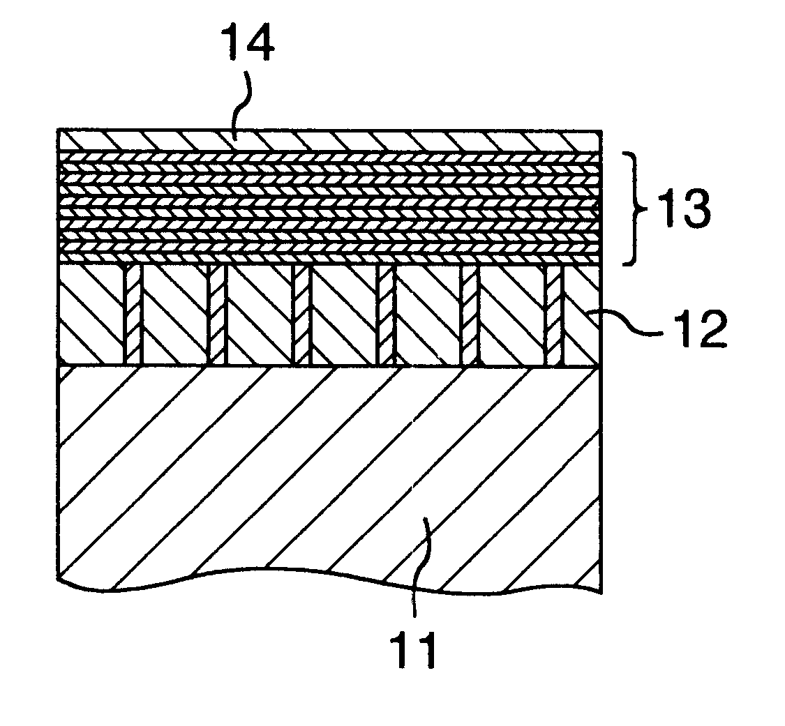
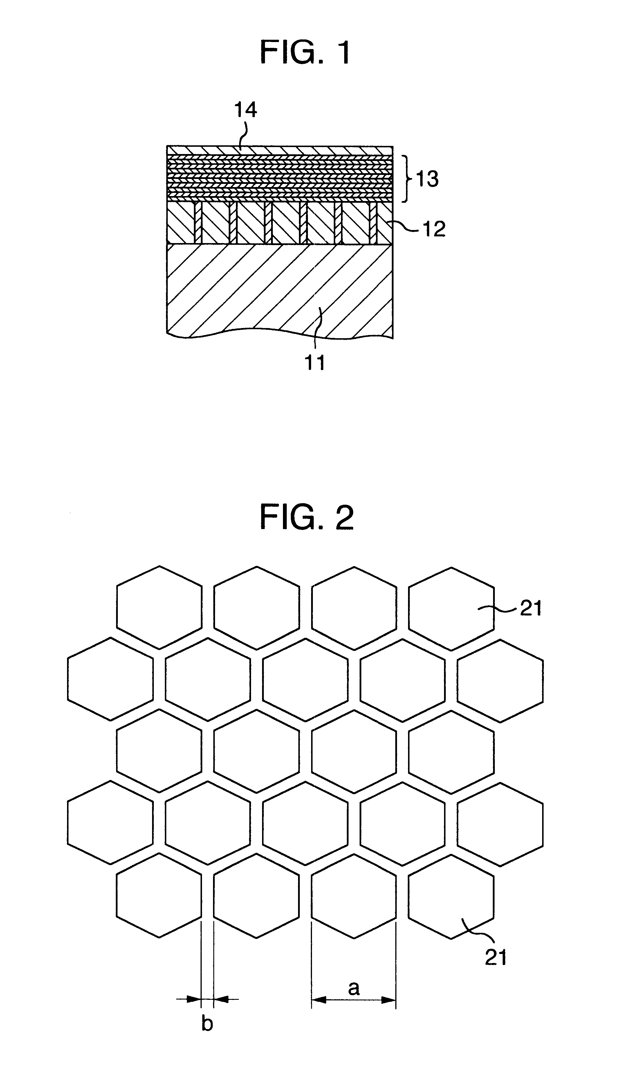
FIG. 1 is a cross sectional schematic diagram of the manufactured magnetic recording disk. The magnetic recording disk has a laminated structure obtained by sequentially forming an inorganic compound layer 12, a magnetic layer 13, and a protective layer 14 onto a substrate 11. A glass substrate having a diameter of 2.5 inches is used as a substrate 11 for the magnetic recording disk. An object obtained by mixing CoO and SiO.sub.2 at a mol ratio of 2:1 is used as a target, pure Ar is used as a discharge gas, and the inorganic compound layer 12 is formed on the substrate 11 by a sputtering method. A thickness of the formed inorganic compound layer 12 is equal to 30 nm. An Ar pressure upon sputtering is equal to 3 mTorr and an input RF electri...

embodiment 2

[Embodiment 2]

An information recording media for magneto-optical recording (hereinafter, referred to as a magneto-optical recording disk) is manufactured. A magneto-optical recording disk drive in which such a magneto-optical recording disk has been assembled is formed.

FIG. 6 is a cross sectional schematic diagram of the manufactured magneto-optical recording disk. The magneto-optical recording disk has a laminated structure obtained by sequentially forming an inorganic compound layer 42, a magnetic layer 43, a magneto-optical enhancement layer 44, and a light reflecting layer 45 onto a substrate 41. A polycarbonate substrate having a diameter of 130 mm in which a guide groove is formed on the surface is used as a substrate 41. To remove the moisture contained in the substrate, the substrate 41 is subjected to a baking treatment in the vacuum for three hours prior to forming a layer. Subsequently, the inorganic compound layer 42 is formed on the substrate 41 by a sputtering method. ...


PUM

PropertyMeasurementUnit
thicknessaaaaaaaaaa
diameteraaaaaaaaaa
thicknessaaaaaaaaaa

Abstract

A magneto-optical storage apparatus including an ultra-high density information recording media having an inorganic compound layer 12 on a substrate 11, and in the inorganic compound layer 12, an oxide of at least one kind selected from silicon oxide, aluminum oxide, titanium oxide, tantalum oxide, and zinc oxide exists in an amorphous state at a grain boundary of crystal grain of an oxide of at least one kind selected from cobalt oxide, iron oxide, and nickel oxide. The media has a magnetic layer 13 made of an artificial lattice multilayer obtained by alternately laminating a Co layer or an alloy layer consisting of Co as a main phase and a metal element layer of at least one kind selected from Pt and Pd onto the layer 12. Thus, a distribution of magnetic properties serving as a pinning site of the movement of a magnetic wall in case of recording information to the magnetic layer 13 is formed in the magnetic layer 13.

Description

The invention relates to an information recording media for promptly and accurately storing a large amount of information and, more particularly, to an information recording media for use as an information recording disk having high performance and high reliability and a magnetic storage apparatus and an magneto-optical storage apparatus using such a media.DESCRIPTION OF THE RELATED ARTThe progress of the recent advanced information society is remarkable and a multimedia in which information of various formats has been integrated is being rapidly spread. As an information recording apparatus which supports it, there are a magnetic recording disk drive and a magneto-optical recording disk drive. At present, in the magnetic recording disk drive, miniaturization is being realized while improving a recording density. In association with it, the realization of a low price of the disk drive is being rapidly progressed. To realize a high density of the magnetic recording disk, techniques (...

Claims


Application Information

Patent Timeline
Patent Type & Authority Patents(United States)
IPC IPC(8): G11B11/00G11B11/10G11B5/70G11B5/62G11B5/66G11B5/738B32B3/06B32B9/00G11B5/64G11B5/65G11B5/673G11B5/73G11B11/105
CPCG11B5/66G11B5/7325G11B11/10586G11B11/10584G11B5/656Y10T428/265Y10S428/90G11B5/7371G11B5/7377
Inventor KIRINO, FUMIYOSHIINABA, NOBUYUKIYAMAMOTO, HIROKINAITOU, TAKASHITAKAHASHI, KENKOYAMA, EIJITERAO, MOTOYASUHOSAKA, SUMIOKURAMOTO, HIROKI
Owner HITACHI GLOBAL STORAGE TECH JAPAN LTD
Why Eureka
Try Eureka