Alternating current driven type plasma display device and method for the production thereof

a technology of alternating current and display device, which is applied in the manufacture of electrode systems, discharge tubes luminescnet screens, instruments, etc., can solve the problems of reducing efficiency, increasing discharge starting voltage or discharge sustaining voltage, and 2 equal 1/2, so as to achieve efficient light emission, higher density pixels, and the effect of improving efficiency

Inactive Publication Date: 2003-04-01
SONY CORP
View PDF10 Cites 14 Cited by
  • Summary
  • Abstract
  • Description
  • Claims
  • Application Information

AI Technical Summary

Benefits of technology

It is, therefore, an object of the present invention to provide a plasma display device that can achieve efficient light emission, causes no increase in discharge starting voltage and discharge sustain voltage and is almost free of dielectric breakdown and abnormal discharge, even if the distance between the separation walls are decreased for realizing higher-density pixels and higher fineness, and a method for the production thereof.
In the present invention, since the recess is formed in the first substrate between a pair of the first electrodes for generating discharge, the discharge space can be increased in volume and the route (path) from one of a pair of the first electrodes to the other can be increased.

Problems solved by technology

Since, however, the separation walls 25 are required to have certain strength for preventing failures, such as chipping during the formation of the separation walls, it involves some difficulty that the value of W.sub.2 equals 1 / 2 of W.sub.1.
As the volume of the discharge cell decreases as described above, the number of metastable particles (the rare gas atoms, molecules, dimers, etc., in a metastable state in the discharge space) required for starting and sustaining discharge decreases, which results in an increase in the discharge starting voltage or discharge sustaining voltage and causes a decrease in efficiency.
Further, the distance between a pair of the facing first electrodes 12A and 12B decreases, and as a result, leak current is liable to flow and dielectric breakdown or abnormal discharge is liable to take place.
Furthermore, since it is required to decrease the thickness of each of the separation walls 25, the separation walls 25 are liable to be damaged during fabrication.

Method used


Image

  • Alternating current driven type plasma display device and method for the production thereof
  • Alternating current driven type plasma display device and method for the production thereof
  • Alternating current driven type plasma display device and method for the production thereof

Examples


example 1

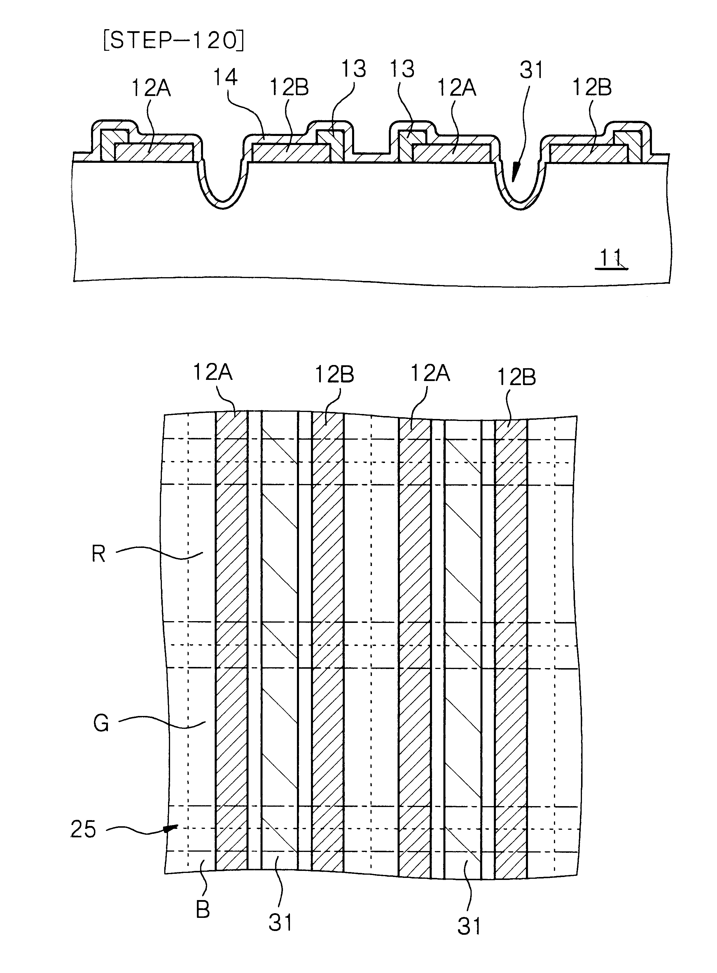
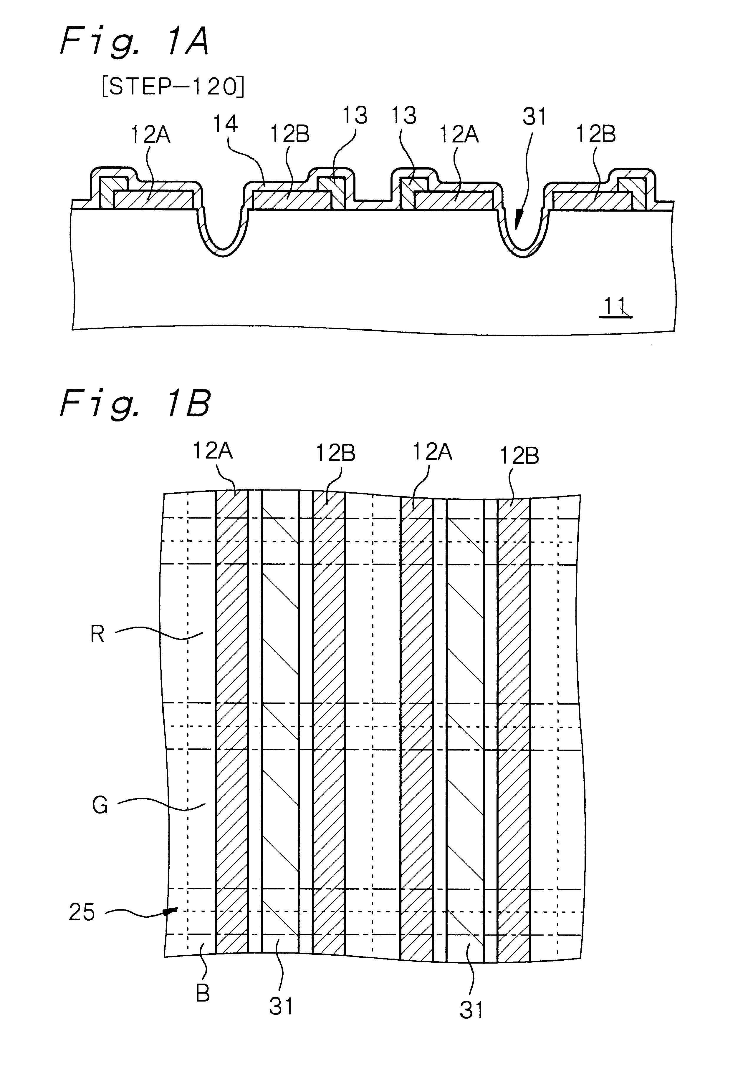
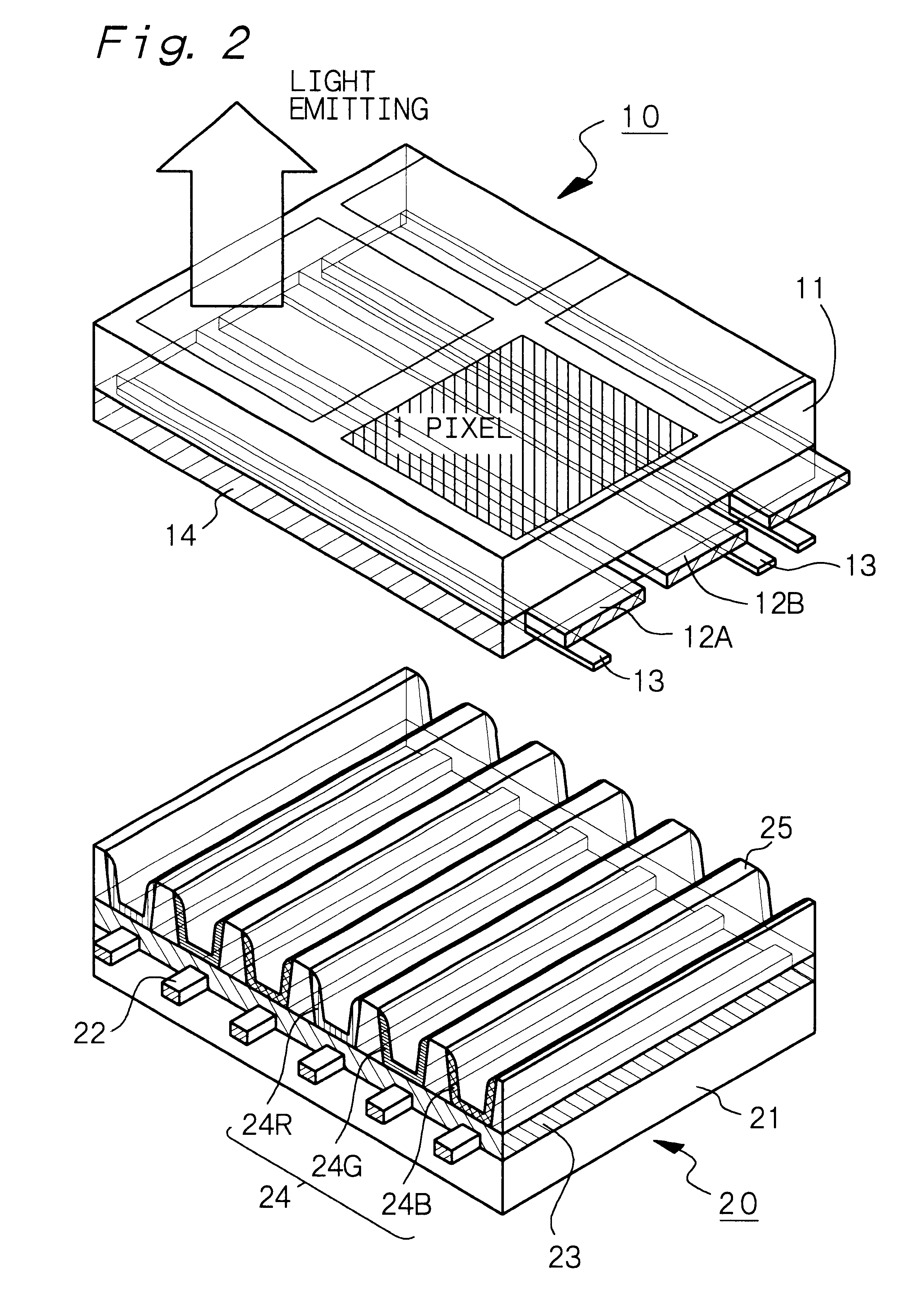
is concerned with the alternating current driven type plasma display device of the present invention and the method for the production of an alternating current driven type plasma display device according to the first aspect of the present invention. The schematic exploded perspective view of the plasma display device of Example 1 is generally as shown in FIG. 2. The plasma display device has a front panel 10 as a first panel and a rear panel 20 as a second panel. The front panel 10 comprises a first substrate 11 made, for example, of glass, a first electrode group constituted of a plurality of first electrodes 12A and 12B formed on the first substrate 11, and a protective layer 14 formed on the first substrate 11 and on the first electrode group. In edge portions of the first electrodes 12A and 12B, bus electrodes 13 extending in parallel with the first electrodes 12A and 12B are formed.

The rear panel 20 comprises a second substrate 21 made, for example, of glass, a second electrod...

example 2

Example 2 is concerned with the method for the production of an alternating current driven type plasma display device according to the second aspect of the present invention. Since the plasma display device produced in Example 2 is substantially structurally the same as the plasma display device explained in Example 1, detailed explanations thereof are omitted. The method for producing the front panel 10 as the first panel in the method for the production of an alternating current driven type plasma display device of Example 2 will be explained below with reference to the schematic partial cross-sectional views of the first substrate 11, etc., shown in FIGS. 8A, 8B, 8C, 9A and 9B.

[Step-200]

First, a conductive material layer 112 is formed on the first substrate 11. Specifically, the conductive material layer 112 composed of ITO is formed on the entire surface of the first substrate 11, for example, by a sputtering method. Then, a Cr / Cu / Cr stacked film is formed on the entire surface ...

example 3

Example 3 is concerned with the method for the production of an alternating current driven type plasma display device according to the third aspect of the present invention. Since the plasma display device produced in Example 3 is substantially structurally the same as the plasma display device explained in Example 1, detailed explanations thereof are omitted. The method for producing the front panel 10 as the first panel in method for the production of an alternating current driven type plasma display device of Example 3 will be explained below with reference to the schematic partial cross-sectional views of the first substrate 11, etc., shown in FIGS. 11A, 11B and 11C.

[Step-300]

First, a recess is formed in a portion of the first substrate that is interposed between regions where a pair of the facing first electrodes are to be formed (see FIG. 11A). The recess can be formed by a chemical method, such as a wet etching method or a dry etching method, whereby the recess 31 constituted...


PUM


Abstract

An alternating current driven type plasma display device having (a) a first panel comprising a first substrate; a first electrode group constituted of a plurality of first electrodes formed on the first substrate and a protective layer formed on the first electrode group and on the first substrate and (b) a second panel comprising a second substrate fluorescence layers formed on or above the second substrate; and separation walls which extend in the direction making a predetermined angle with the extending direction of the first electrodes and each of which is formed between one fluorescence layer and another neighboring fluorescence layer, wherein discharge is caused between each pair of the first electrodes facing each other, and a recess is formed in the first substrate between each pair of the facing first electrodes.

Description

BACKGROUND OF THE INVENTION AND RELATED ART STATEMENTThe present invention relates to an alternating current driven type plasma display device and a method for the production thereof.As an image display device that can be substituted for a currently mainstream cathode ray tube (CRT), flat-screen (flat-panel) display devices are studied in various ways. Such fat-panel display devices include a liquid crystal display (LCD), an electroluminescence display (ELD) and a plasma display device (PDP). Of these, the plasma display device has advantages that it is relatively easy to form a larger screen and attain a wider viewing angle, it has excellent durability against environmental factors such as temperatures, magnetism, vibrations, etc., and it has a long lifetime. The plasma display device is therefore expected to be applicable not only to a home-use, wall-hung television set but also to a large-sized public information terminal.In the plasma display device, a voltage is applied to disc...

Claims


Application Information

Patent Timeline
Patent Type & Authority Patents(United States)
IPC IPC(8): H01J9/02H01J17/49H01J11/12H01J11/14H01J11/22H01J11/24H01J11/26H01J11/34
CPCH01J9/02H01J9/241H01J11/38H01J11/34H01J11/12H01J11/40
Inventor SHIROZU, SHINICHIRO
Owner SONY CORP
Why Eureka
Try Eureka