Color-shifting pigments and foils with luminescent coatings

a technology of luminescent coating and pigment, applied in the field of color-shifting pigments and foils with luminescent coating, can solve the problems of difficult use together, performance of prior color-shifting/luminescent inks, and thin film particles that do not have color-shifting properties, etc., to achieve the effect of increasing the value of color-shifting pigment products, not easily duplicated, and increasing thermal stability, mechanical stability and durability

Inactive Publication Date: 2003-05-20
VIAVI SOLUTIONS INC
View PDF78 Cites 316 Cited by
  • Summary
  • Abstract
  • Description
  • Claims
  • Application Information

AI Technical Summary

Benefits of technology

The present invention provides numerous advantages and benefits. Primarily, the present invention provides pigment or foil components for security devices which have distinct and pronounced overt and covert features under visible wavelength and non-visible wavelength light sources. These distinct features are not easily duplicated and cannot be copied by simple mixtures of interference pigments and luminescent materials. Another advantage is that the covert features are machine readable, yet coexist with overt features such as the color-shifting nature of the materials. Thus, although it may be apparent that security features exist, it is not apparent how many security features are present. Further, the covert features can selectively code additional information.
The luminescence feature adds to the value of color-shifting pigment products by potentially increasing thermal stability, mechanical stability, and durability. This feature also provides light fastness, as wel

Problems solved by technology

Nevertheless, the thin film particles do not themselves have color-shifting properties.
Unfortunately, the performance of prior color-shifting/luminescent inks has several drawbacks.
The color-shifting flakes and luminescent particles also tend to be incompatible with the same ink or coating vehicle, making them difficult to use together.
Further, the luminescent particles tend to opacify and dull the color performance of the color-shifting flakes.
Additionally, the simple physical mixing of separate color-shifting and l

Method used


Image

  • Color-shifting pigments and foils with luminescent coatings
  • Color-shifting pigments and foils with luminescent coatings
  • Color-shifting pigments and foils with luminescent coatings

Examples


example 2

FIG. 13 is a graph illustrating the angle-sensitive emission 320 of a luminescent color-shifting pigment according to the invention. The graph illustrates how changes in the incident angle of electromagnetic energy results in different emission levels. As shown, there exists a peak 322 of maximum absorption that corresponds to a particular wavelength. Thus, a given luminescent material will highly absorb at one angle of incidence but not at others. This feature of the invention allows for further customization and differentiation of luminescent color-shifting pigments and foils.

example 3

A luminescent color-shifting pigment of the invention was produced by a sol-gel process. A batch of color shifting flakes were over-coated with a layer of silicon dioxide that was sol-gel doped with a luminescent dye. In this approach, the molecules of the luminescent dye covalently bonded to the sol-gel matrix. The sol-gel coating solution had the following components:

3.0 g of 96% ethanol

1.0 g of 99+ tetraethyl-ortho-silicate (TEOS)

0.4 g of 0.1M HCl

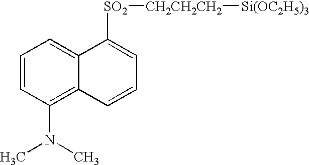
0.5 g of a fluorescent dye having the chemical structure shown below and the chemical name of 5-dimethylamino-N-(3-triethoxysilyl-propyl)naphthalene-1-sulfonamide. ##STR1##

After combining all ingredients the coating solution was kept for 30 minutes at 80.degree. C. under continuous stirring. Then 0.5 g of the color shifting pigment was added to the solution and the mixture was exposed to an additional 30 minutes of stirring at 80.degree. C. After this process step the flakes of the coated pigment were filtered out on a Buchner funnel, ri...

example 4

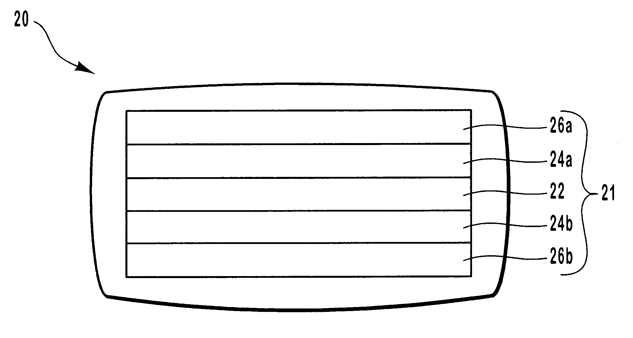
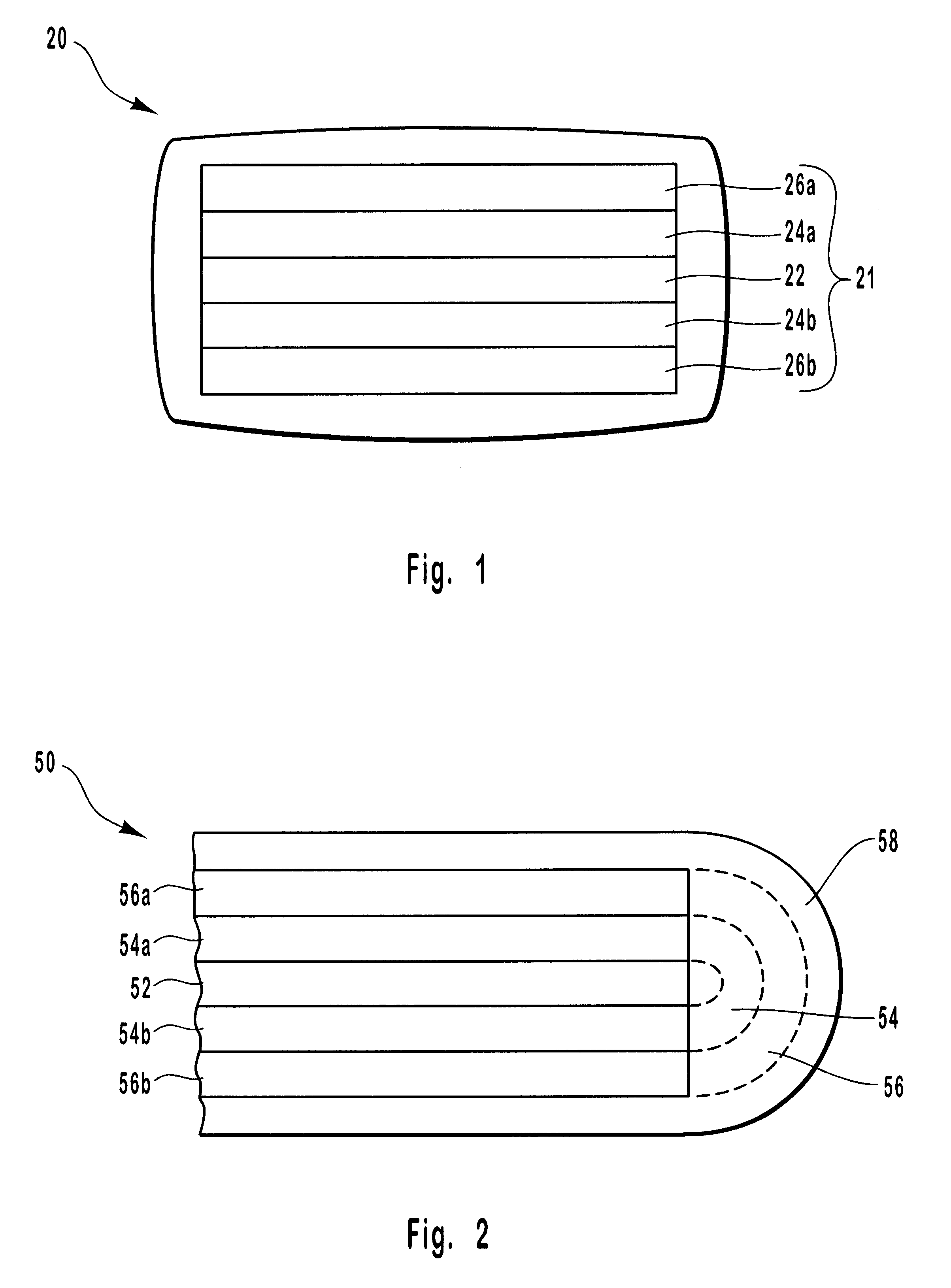
A luminescent color-shifting pigment was produced by a sol-gel process similar to that described in Example 3. The flakes of the pigment had a multilayer structure similar to flake 20 of FIG. 1. The luminescent response of this pigment was measured by using two different illuminating wavelengths. These included a short wavelength excitation having a spectral radiance peaked at 406 nm (short), and a long wavelength excitation having a spectral radiance peaked at 524 nm (long).

Table 1 below summarizes the spectral response (sr) intensity of the pigment in Watt / sr / m.sup.2 for each excitation wavelength over the visible spectrum (420-780 nm) in 10 nm increments. Table 1 lists the measured background intensity along with the measured luminescent intensity of the pigment at the short and long wavelengths both before (short, long) and after adjustment for the background intensity (short-bk, long-bk). The adjustment was made by subtracting the measured background intensity from the measured...


PUM

PropertyMeasurementUnit
Lengthaaaaaaaaaa
Lengthaaaaaaaaaa
Thicknessaaaaaaaaaa

Abstract

Interference pigment flakes and foils are provided which have luminescent and color-shifting properties. A luminescent material coating structure is provided which partially covers or encapsulates a color-shifting pigment flake, or covers the outer surface of a foil. The pigment flakes can have a symmetrical coating structure on opposing sides of a core layer, can have an asymmetrical coating structure with all of the layers on one side of the core layer, or can be formed with encapsulating coatings around the core layer. The coating structure of the flakes and foils includes a core layer, a dielectric layer overlying the core layer, and an absorber layer overlying the dielectric layer. The luminescent pigment flakes and foils exhibit a discrete color shift so as to have a first color at a first angle of incident light or viewing and a second color different from the first color at a second angle of incident light or viewing. The luminescent pigment flakes can be interspersed into liquid media such as paints or inks to produce colorant materials for subsequent application to objects or papers. The luminescent foils can be laminated to various objects or can be formed on a carrier substrate.

Description

1. Field of the InventionThe present invention relates generally to optical effect pigments and foils. More particularly, the present invention relates to optically variable pigment flakes and foils with luminescent coatings.2. Background TechnologyVarious color-shifting pigments, colorants, and foils have been developed for a wide variety of applications. For example, color-shifting pigments have been used in applications such as cosmetics, inks, coating materials, ornaments, ceramics, automobile paints, anti-counterfeiting hot stamps and anti-counterfeiting inks for security documents and currency. Such pigments, colorants, and foils exhibit the property of changing color upon variation of the angle of incident light, or as the viewing angle of the observer is shifted.The color-shifting properties of the pigments and foils can be controlled through proper design of the optical thin films or orientation of the molecular species used to form the flake or foil coating structure. Desi...

Claims


Application Information

Patent Timeline
IPC IPC(8): C09C1/00
CPCB82Y10/00B82Y30/00C09C1/0015C09K11/06C09C2200/1054C09C2200/20C09K2211/1011C09C2200/409C09C2210/50C09C2220/10C09C2220/20C09C2200/306C01P2004/20C01P2004/84
Inventor MAYER, THOMASYAMANAKA, STACEY A.ZIEBA, JAROSLAW
Owner VIAVI SOLUTIONS INC
Why Eureka
Try Eureka