Single mode optical fibre having a large cone photonic crystal

a single-mode optical fibre and cone technology, applied in the field of single-mode optical fibres, can solve the problems of limiting the amount of light that can be carried by known optical fibres at a given time, material from which the fibre is made will ultimately suffer irreversible damage, degrade or even destroy an optical signal,

Inactive Publication Date: 2003-08-05
NKT RES & INNOVATION
View PDF5 Cites 39 Cited by
  • Summary
  • Abstract
  • Description
  • Claims
  • Application Information

AI Technical Summary

Benefits of technology

Optical fibres are widely used to deliver light from one point to another and have application in communications, imaging and sensing. Conventionally, a typical optical fibre is a long strand of transparent material which is uniform along its length but which has a refractive index varying across its cross-section. For example, a central core region of higher refractive index is surrounded by a cladding region with a lower refractive index. Such a fibre may be made from fused silica with a cladding of pure silica surrounding a core made from silica into which deliberate impurities have been introduced to raise the refractive index. Light is confined in or near the core by the process of total internal reflection which takes place at the boundary between the core and the cladding.

Problems solved by technology

There are, however, limits to the amount of light that can be carried by known optical fibres at a given time.
In a conventional fibre, comprising a core region surrounded by a lower refractive index cladding region, the material from which the fibre is made will ultimately suffer irreversible damage if the light intensity within the fibre exceeds a threshold value.
At lower intensities, a number of intensity dependent non-linear optical processes can occur which, although non destructive to the fibre, nevertheless can degrade or even destroy an optical signal.
Eventually, however, it becomes difficult to control the uniformity of doping across the core.
Furthermore, fibres with small index differences are susceptible to loss of light at bends.
Therefore, there are limits to the extent to which an increased core size can be used to increase the power capacity of a single mode fibre.
Some of the non-linear effects are exacerbated by the presence of dopants in the core, which make the material more susceptible to these effects.
At higher powers, doped fibres are more susceptible to irreversible damage.
Dopants also make the fibre more susceptible to damage by ionising radiation which is an issue in the nuclear industry.
However, this is limited by the fact that some of the light is carried in the doped cladding.
Furthermore, in conventional fibres, efficient coupling of high power lasers into the fibre is problematic as the light needs to be focused into a small spot and the intensity at the endface of the fibre is therefore larger than it would be if the core were larger.

Method used


Image

  • Single mode optical fibre having a large cone photonic crystal
  • Single mode optical fibre having a large cone photonic crystal
  • Single mode optical fibre having a large cone photonic crystal

Examples


Embodiment Construction

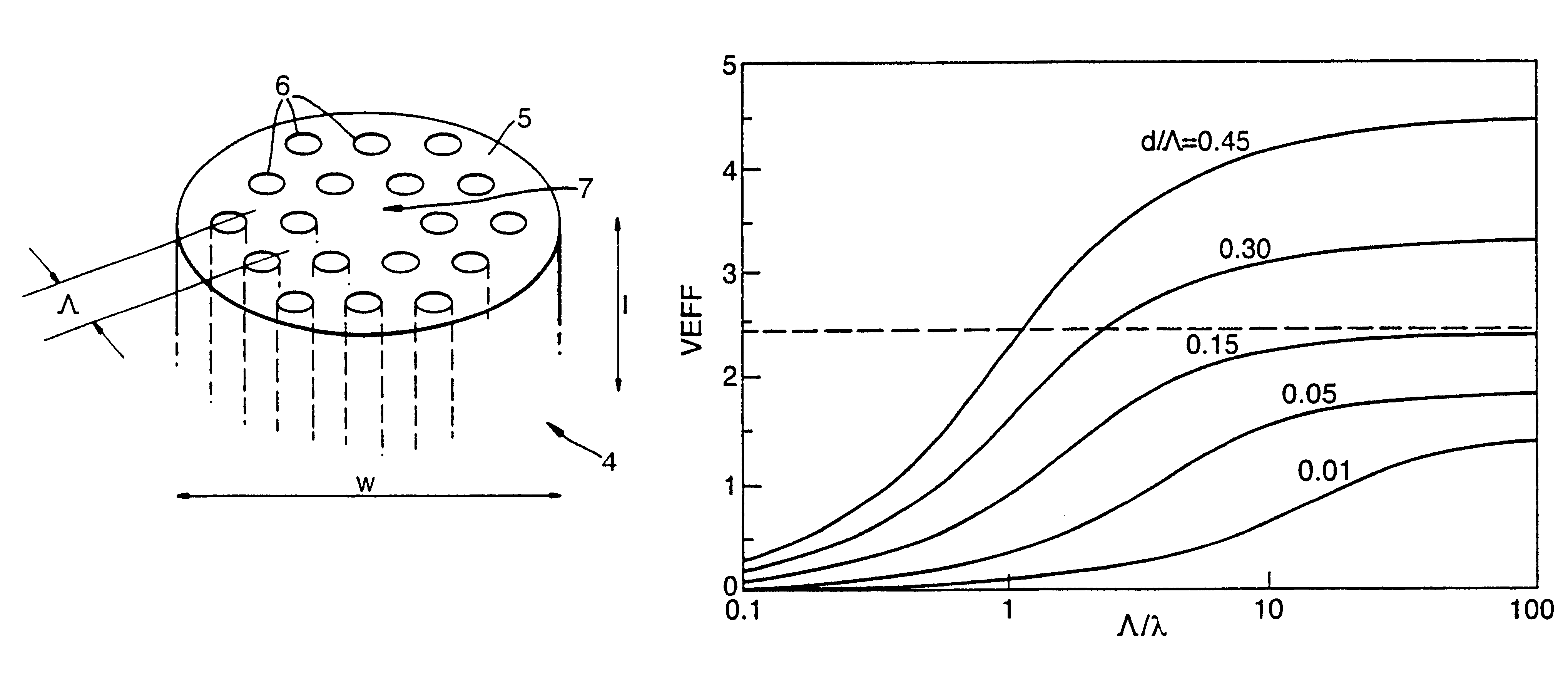
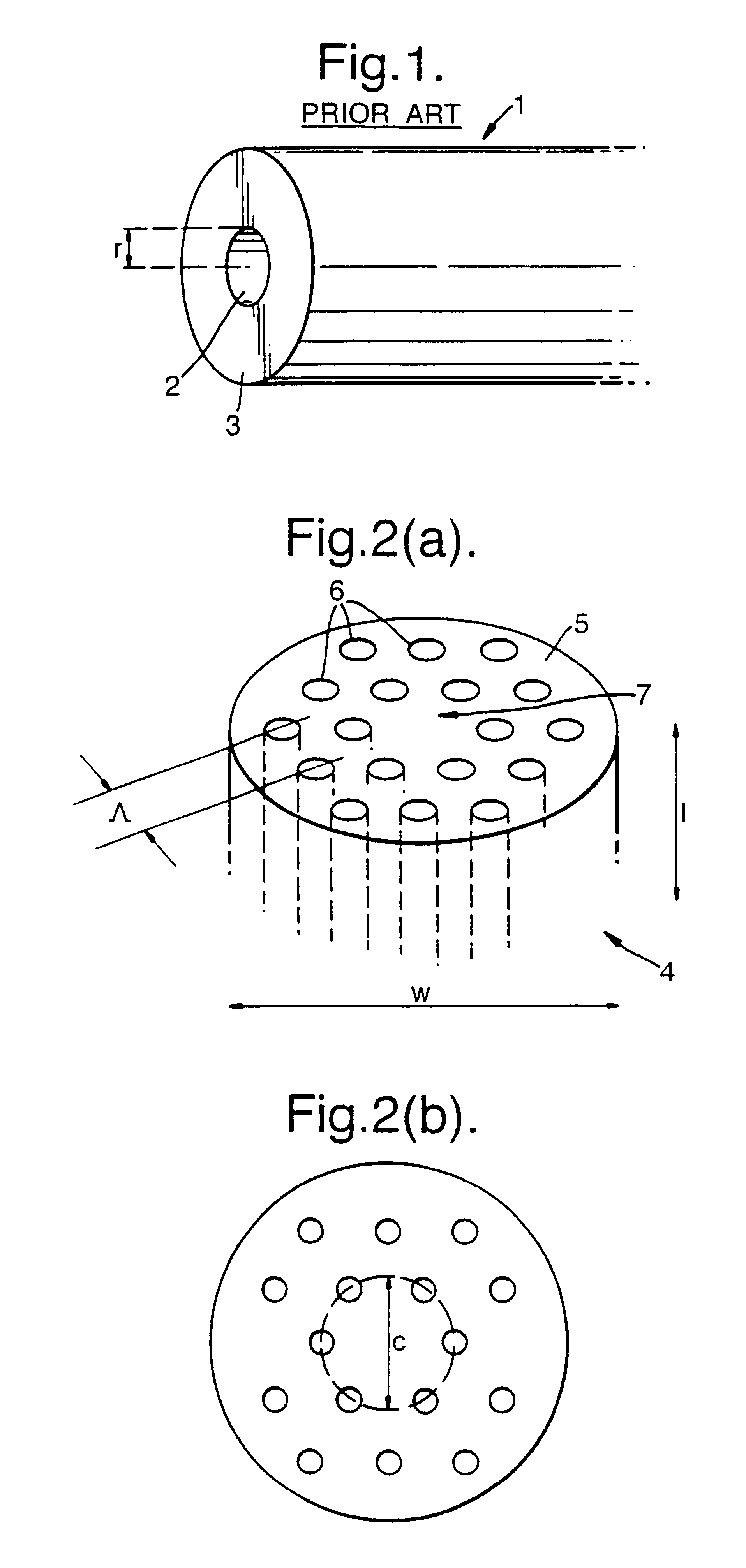
Referring to FIG. 1, a conventional step index fibre 1 comprises a circular core 2 of uniform refractive index n.sub.1 and radius r surrounded by a cladding material 3 of uniform refractive index n.sub.2. The number of guided modes the step index fibre 1 supports for light of wavelength .lambda. is determined by the V-value, where V is given by; ##EQU1##

The step index fibre is single mode only if V is less than 2.405. Hence, conventional single mode step index fibres are typically operated so that V is a little less then 2.405.

Note: The threshold level V for multi mode propagation in large core photonic crystal fibres is different to the threshold value for conventional single mode step index fibres. In practice the threshold level for multi mode propagation in a large core photonic crystal fibre is somewhat higher than the value for a conventional single mode step index fibre.

In a conventional step index optical fibre, such as that shown in FIG. 1, the material from which the fibre...


PUM

PropertyMeasurementUnit
diameteraaaaaaaaaa
core diameteraaaaaaaaaa

Abstract

A large core photonic crystal fiber for transmitting radiation having a core comprising a substantially transparent core material and having a core diameter of at least 5mu. The fiber also comprises a cladding region surrounding the length of core material, wherein the cladding region comprises a first substantially transparent cladding material, having a first refractive index, and wherein the first substantially transparent cladding material has embedded along its length a substantially periodic array of holes, wherein the holes are filled with a second cladding material having a second refractive index less than the first refractive index, such that radiation input to the optical fiber is transmitted along the length of the core material in a single mode of propagation. In a preferred embodiment, the core diameter may be at least 20mu, and may be as large as 50mu. The fiber is capable of transmitting higher power radiation than conventional fibers, whilst maintaining propagation in a single mode. The core material may be doped with a material capable of providing amplification under the action of pump radiation input to the fiber. The invention also relates to a fiber amplifier and a fiber laser comprising a doped large core photonic crystal fiber. The fibre may also be used in a system for transmitting radiation comprising a plurality of lengths of large core photonic crystal fiber, separated by large core photonic crystal fiber amplifiers, such that the power of radiation transmitted through the system is maintained above a predetermined threshold power.

Description

1. Field of the InventionThe invention relates to a single mode optical fibre which may be used for transmitting radiation at substantially higher powers than may be achieved using conventional means. The fibre does not suffer from non linear effects or optical damage at high powers to the same extent as conventional optical fibres. In particular, the fibre may be used as a single mode waveguide, in a single mode fibre laser or in a single mode fibre amplifier.2. Discussion of Prior ArtOptical fibres are widely used to deliver light from one point to another and have application in communications, imaging and sensing. Conventionally, a typical optical fibre is a long strand of transparent material which is uniform along its length but which has a refractive index varying across its cross-section. For example, a central core region of higher refractive index is surrounded by a cladding region with a lower refractive index. Such a fibre may be made from fused silica with a cladding of...

Claims


Application Information

Patent Timeline
Patent Type & Authority Patents(United States)
IPC IPC(8): C03B37/012G02B6/42H01S3/06H01S3/067G02B6/00G02B6/02G02B6/032G02B6/122H01S3/10
CPCB82Y20/00C03B37/01205G02B6/02G02B6/02333G02B6/02347G02B6/02361G02B6/02371G02B6/1225G02B6/4296H01S3/06708C03B2201/34C03B2203/14C03B2203/42G02B6/02385
Inventor BIRKS, TIMOTHY AKNIGHT, JONATHAN CRUSSELL, PHILIP ST J
Owner NKT RES & INNOVATION
Why Eureka
Try Eureka