Laser microscope and confocal laser scanning microscope

a laser scanning microscope and laser microscope technology, applied in the field of laser microscope and confocal laser scanning microscope, can solve the problems of shortening the integrated circuit, compromising the ease of use, and operating wavelength

Inactive Publication Date: 2003-09-16
NIKON CORP
View PDF12 Cites 15 Cited by
  • Summary
  • Abstract
  • Description
  • Claims
  • Application Information

AI Technical Summary

Problems solved by technology

Under normal circumstances, the use of immersion objective lenses is not desirable since oil would adhere to the sample to result in oxidation of metal wirings thereby inducing problems such as shorting of the integrated circuit.
However, the reduction in the operating wavelength would complicate the structure and the operation of a microscope system that operates in the wavelength range of X rays or electron beams, which is bound to compromise the ease of use and, therefore, there is a limit to the degree to which the operating wavelength can be reduced.
In the case of an ultra-fine cyclical structure ("line and space" is terminology normally used in the semiconductor process technology), it becomes logically difficult to resolve a cyclical structure in the sample with its repetitive cycle smaller than 0.25 .mu.m with good contrast on a conventional optical

Method used


Image

  • Laser microscope and confocal laser scanning microscope
  • Laser microscope and confocal laser scanning microscope
  • Laser microscope and confocal laser scanning microscope

Examples


first embodiment

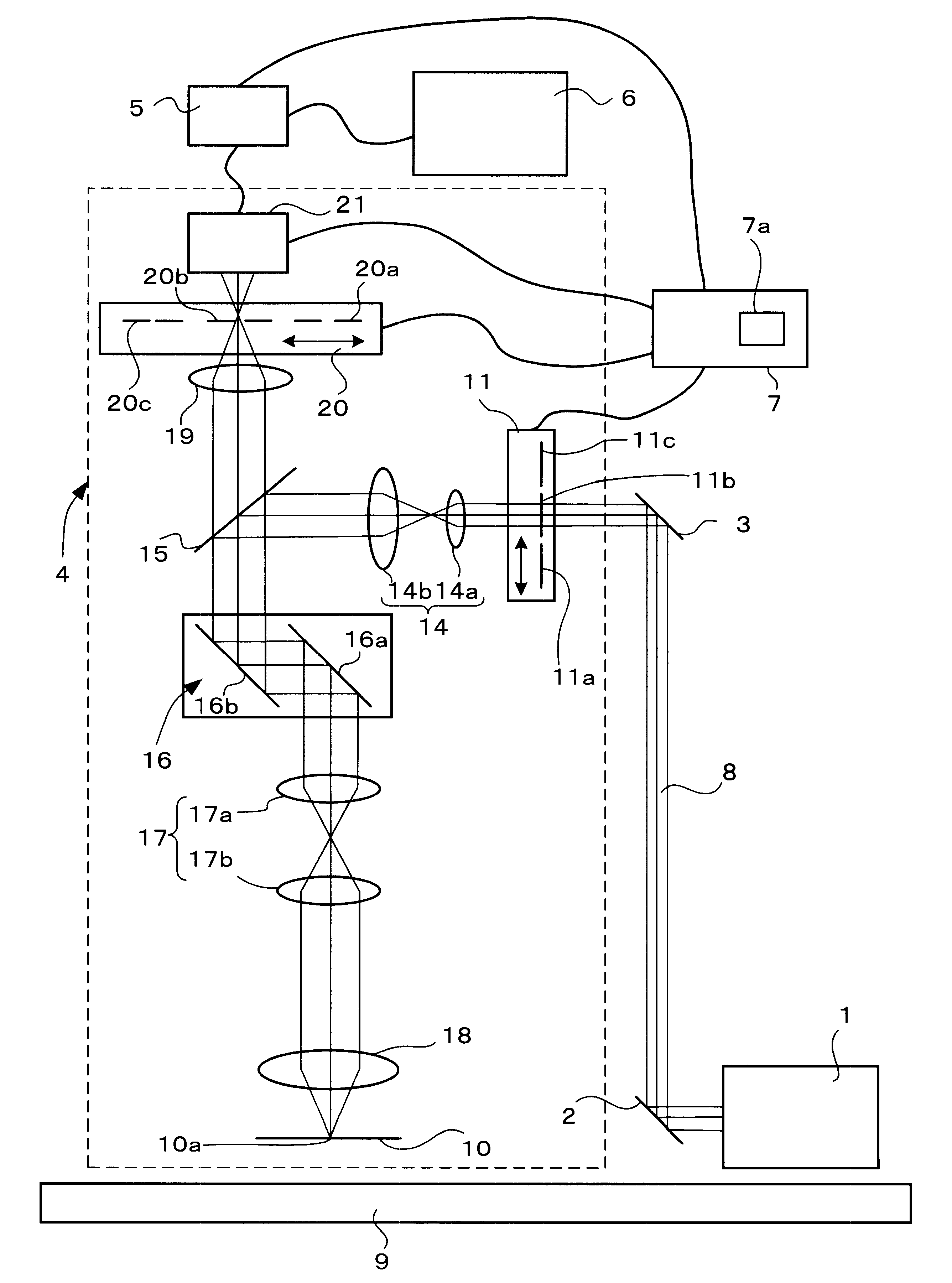
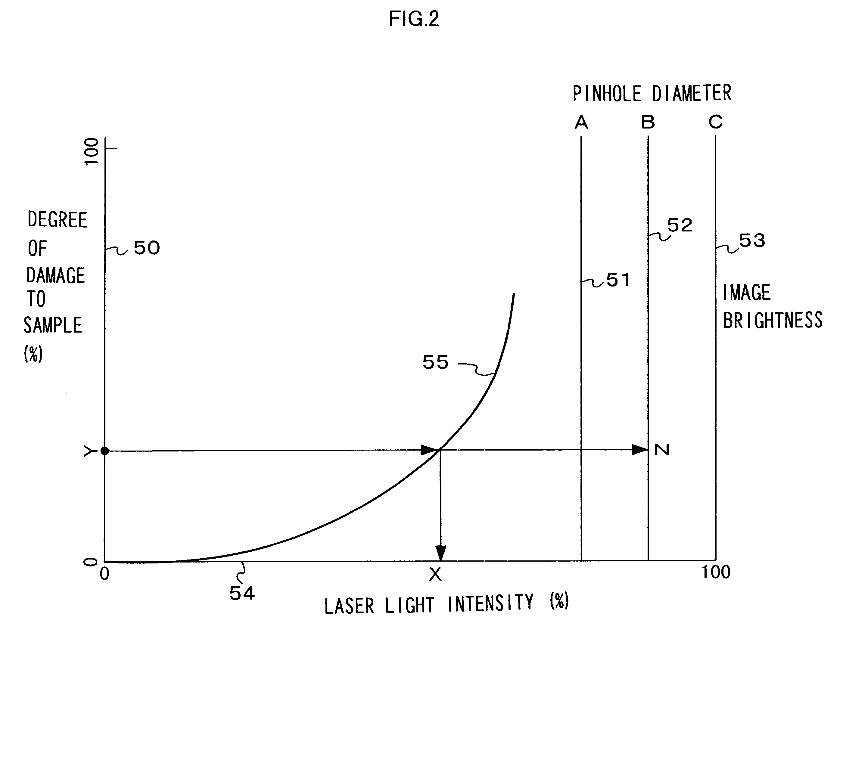
FIG. 1 is a block diagram of the confocal laser scanning microscope in the present invention and FIG. 2 presents a map indicating the relationships among the degree of damage to the sample, the intensity of the laser light, the pinhole size and the brightness of the image.

The confocal laser scanning microscope comprises a laser light oscillation device 1, i.e., a light source, a reflector 2, a reflector 3, a microscope main unit 4, an image processing device 5, a display 6, a computer 7 and a vibration damping stage 9.

The laser light oscillation device 1 emits laser light in the deep ultraviolet range.

The microscope main unit 4 includes a light-reducing filter switching unit 11, a beam expander 14, a beam splitter 15, a two-dimensional scanner unit 16, a relay lens 17, a first objective lens 18, a first condenser lens 19, a pinhole switching unit 20 and a photomultiplier (photomultiplier tube) 21.

The light-reducing filter switching unit 11 is provided with a plurality of light-reduc...

second embodiment

Moreover, while an explanation is given above in reference to the second embodiment on an example in which the optical fiber 102 is employed as a means for guiding the laser light 8 from the laser light oscillator device 1 to the microscope main unit 104, an optical fiber bundle may be used instead for this purpose.


PUM


Abstract

A laser microscope includes: a light source that emits deep ultraviolet laser light to be irradiated on a sample; a limiting device that sets a limit to an intensity of the deep ultraviolet laser light irradiated on the sample; a detection device that detects the deep ultraviolet laser light having been reflected from the sample; a storage device that stores first information related to damage to the sample corresponding to the intensity of the deep ultraviolet laser light; and a control device that controls the limiting device based upon the first information when a sample damage limit is input from outside.

Description

The disclosure of Japanese Patent Application No. H11-288979 filed Oct. 12, 1999 is herein incorporated by reference.1. Technical FieldThe present invention relates to a laser microscope and a confocal laser scanning microscope.2. Background ArtThe limits to the resolving power of a microscope employed to observe an ultra-fine structure is normally a expressed as .delta.=.lambda. / 2NA with .delta. representing the resolving power, .lambda. representing the operating wavelength and NA representing the numerical aperture at the objective lens. This expression indicates that the resolving power .delta. maybe improved by reducing the operating wavelength .lambda., by increasing the numerical aperture NA at the objective lens or by both reducing the operating wavelength .lambda. and increasing the numerical aperture NA of the objective lens at the same time.When observing a bio-sample (bio-specimen) such as a cell, the resolving power is improved by utilizing an immersion objective lens, ...

Claims


Application Information

Patent Timeline
IPC IPC(8): G02B21/00G02B21/16
CPCG02B21/0024G02B21/0032G02B21/008
Inventor OGINO, KATSUMI
Owner NIKON CORP
Why Eureka
Try Eureka