
Method and device for the detection of microorganisms by fiber optics

a technology of fiber optics and microorganisms, applied in the field of methods and devices for the detection of microorganisms by fiber optics, can solve the problems of other types of microorganisms being intrinsically dangerous, microorganisms not serving any other practical purpose, and microorganisms becoming dangerous, etc., to achieve easy incorporation, easy operation, and the effect of miniaturization

Inactive Publication Date: 2004-04-06
FUNDACAO OSWALDO CRUZ FIOCRUZ +1
View PDF8 Cites 24 Cited by
  • Summary
  • Abstract
  • Description
  • Claims
  • Application Information

AI Technical Summary

Benefits of technology

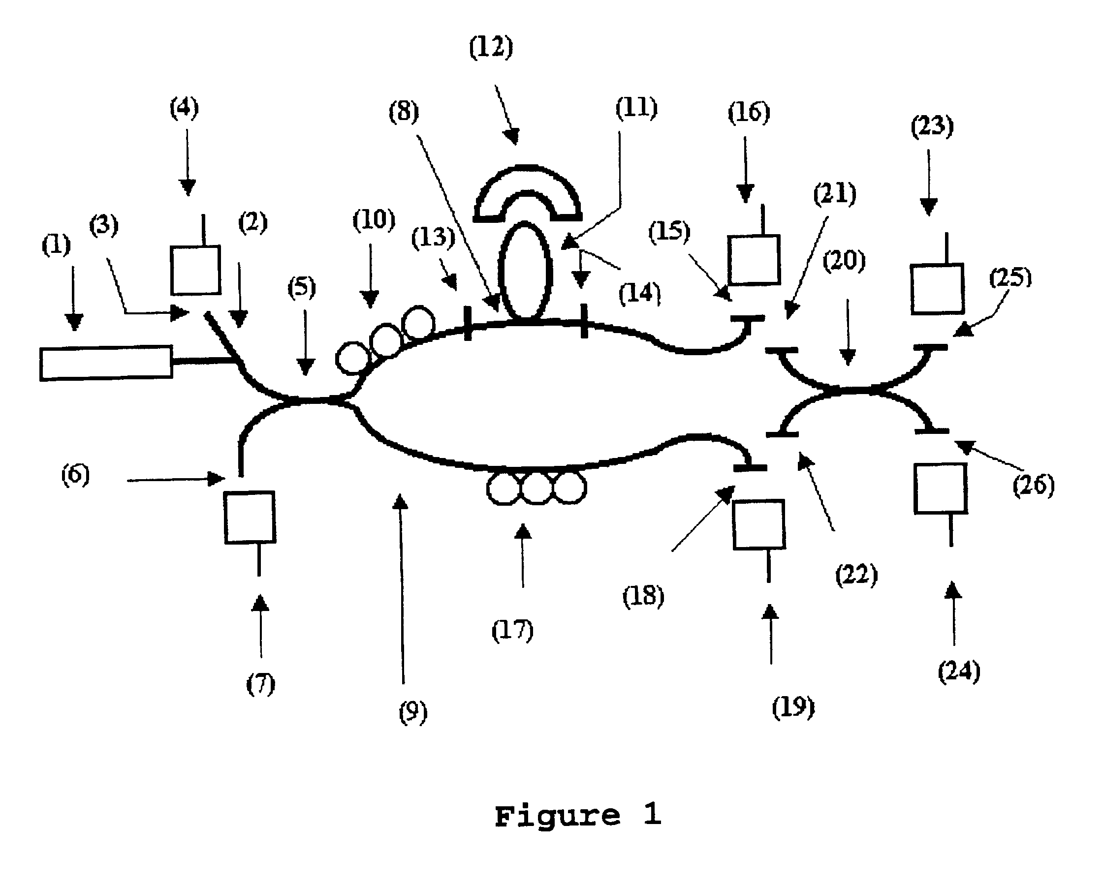
This material medium may also be constituted of fluids of a corporal nature such as water, blood, urine, etc. In this last case, microorganisms may be present and reproduce throughout the volume of the fluid. The segment a of sensitive optical fiber should be conveniently placed on the surface or inserted in the volume of the biological culture medium. Beforehand, however, this fiber shall have an area of its primary covering removed and will undergo a treatment employing an appropriate technique based on chemical and physical properties. This treatment aims to expose the evanescent-field of the optical fiber through etching, for instance, using, preferably, strong acids, such as hydrdfluoric, hydrochloric, sulfuric acids, for instance. It is necessary that the treatment lasts for the time necessary to etch the sheath of the optic fiber to an approximate thickness of 0.5 to 1 .mu.m from the core. In this way, it is possible to expose approximately 80% of the evanescent-field. The etching is interrupted by the immersion of the fiber in deionised water and, afterwards, in a pH stable solution for an adequate time to remove any residue of water. Thus, it is possible to couple the evanescent-field of the means of guided propagation to the material medium containing the subject (microorganisms). The sensitive fiber optic, in turn, is inserted continuously in a larger fiber optic circuit, having a particular assembly with the aim of demodulating the optical signal modulated by the subject. These characteristics confer to the invention operational advantages of biological selectivity, sensitivity, resolution, response velocity, stability, possibility of miniaturization, ease of operation and easy incorporation into larger and more complex optical circuits that are destined to compose a survey network (overall survey) in a manner that microorganisms may be detected / monitored in various places simultaneously. The sensor technology described here should be employed preferably for biological detection / monitoring in a qualitative and / or quantitative manner having a specific microorganism as subject.

Problems solved by technology

Other microorganisms do not seem to serve any other practical purpose, but are, in principle, harmless to human health.
However, some of these microorganisms may become dangerous, for a series of reasons, after undergoing certain types of biological transmutations and whereupon they are termed pathogenic.
Other types of microorganisms may be intrinsically dangerous, meaning that they are naturally constituted as noxious to human health.
These techniques are reasonably complex, as they demand from the operator significant intervention and skill in order to obtain dependable results, and typically require 1 to 10 days for completion.
Apart from which, the conventional techniques use equipment that is not particularly low cost, making its employment difficult or unviable for widespread surveying, in other words, for detection / monitoring of microorganisms in more than one place simultaneously.
Concerning the techniques mentioned, there are some practical restrictions such as, for example, their success is highly dependent on the quantity of bacteria that can be concentrated in the test sample.
In molecular reactions, the test procedures are particularly liable to cross contamination by other molecules or molecular fractions.
On the other hand, the medical knowledge for fighting pathogenic microorganisms that had already infected the human body, especially those originating from hospital infection, food poisoning and water contamination, is vast but incomplete.
However, it presents the disadvantage of the analysis taking approximately 7 to 14 days, as described by Birron and Lai (B. Birron and E. Lai. "Pulsed field electrophoresis: a practical guide".

Method used


Image

  • Method and device for the detection of microorganisms by fiber optics
  • Method and device for the detection of microorganisms by fiber optics
  • Method and device for the detection of microorganisms by fiber optics

Examples


example 2

Obtaining an Air Sample

An air sample is collected through the technique known to experts in the field as impaction-on-a-gel employing Merck MAS-100 equipment. In this manner, a sample of the ambient air was aspirated, through perforated plates, with the aid of a vacuum pump (with a is volumetric flow rate of 100 liters per minute) for 30 seconds. The resulting air stream that carries particles with diameters inferior to 10 .mu.m, was directed to the agar surface of a Petri dish. Eighteen collections were undertaken, during six random days, three collections per day, during two weeks. During the three first days, a specific culture medium for Staphylococcus aureus was used, and during the three remaining days, a specific medium for S. pneumoniae was used.

example 3

Growth of Microorganisms in a Selective Culture Medium

The culture medium used for Staphylococcus aureus resistant to methicillin (MRSA) obtained in Example 2 was the Baird-Parker Agar (Difco Laboratories-Difco 0768-17-3) at an incubation temperature of 35.degree. C. For S. pneumoniae, the culture medium used was Trypticase soya agar (Difco Laboratories, Detroit, Mich.--Difco 0026-17-1) supplemented with sheep blood at 5% at an incubation temperature of 35.degree. C. In both the culture media glycerol at 0.2% was added, so as to avoid drying out the culture during the tests. For the growth of E. coli 0157:H7, the selective culture medium employed was the MacConkey sorbitol agar base (Difco Laboratories-Difco 0079-17-7), at an incubation temperature of 35.degree. C.

Many tests were performed so as to calibrate the biosensor for its selectivity, using different initial values of bacteria (N.sub.0). E. coli 0157:H7 available commercially in lyophilized form was reconstituted with 1.0 mml...

example 4

Correlation of the Growth With the Estimated Number of Bacteria

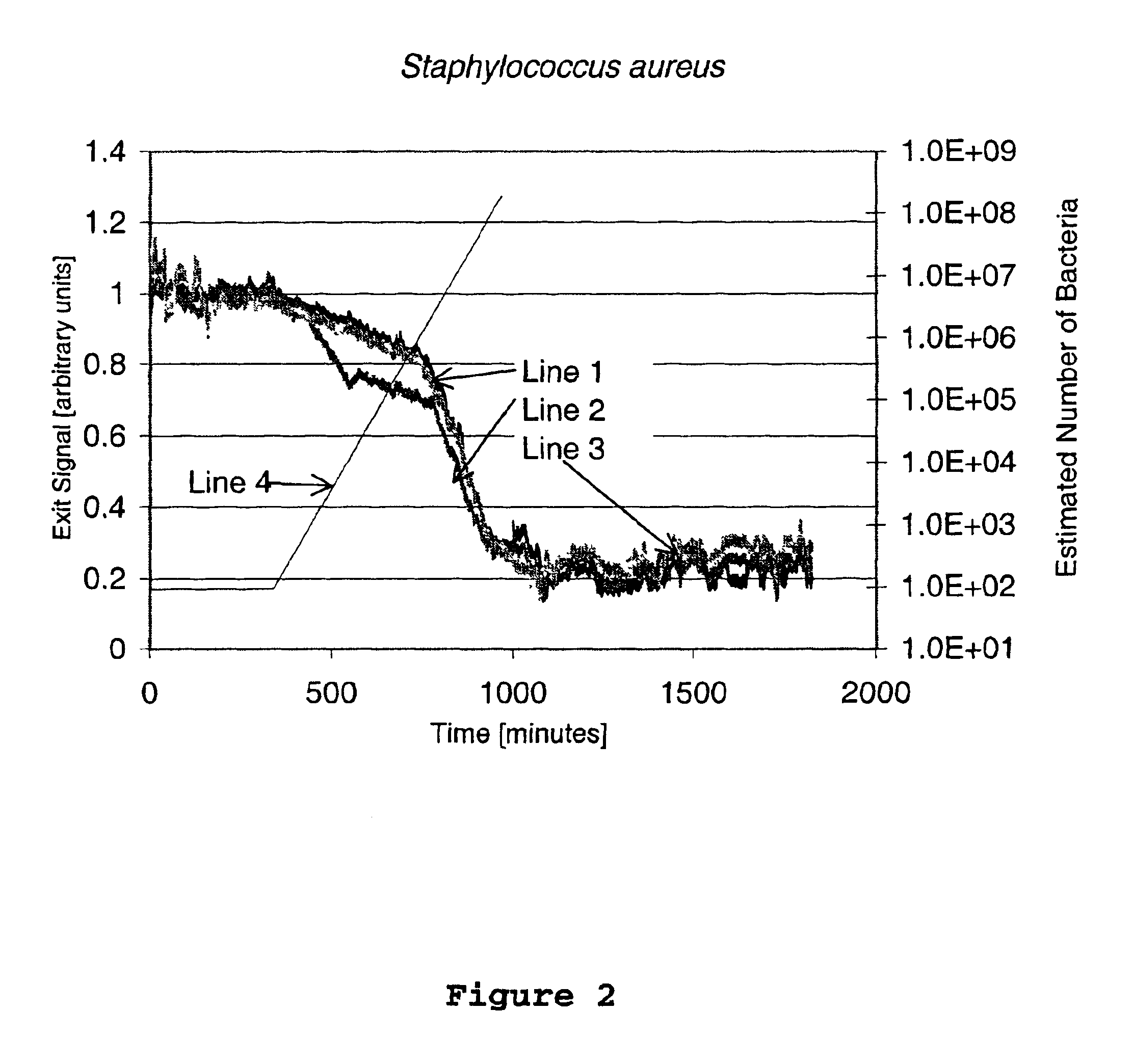
FIGS. 2 and 3 present, respectively, the optical signal of the sensor for Staphylococcus aureus resistant to methicillin and S. pneumoniae. Lines 1, 2 and 3 represent the output signal for samples 1, 2 and 3, respectively. Line 4 correlates the growth with the estimated number of bacteria, in accordance with the following formula:

N(t)=N.sub.0 2.sup.t / GT

where t is the time in minutes, N is the total number of bacteria in the time t, No is the initial number of bacteria (equal to 94 for Staphylococcus aureus resistant to methicillin (MRSA) and 91 for S. pneumoniae) and GT is the time of generation (equal to 30 minutes for MRSA and 48 minutes for S. pneumoniae).

Observing FIGS. 2 and 3, one notes the presence of three distinct phases: the first is a plateau where no response is detected (Lag phase). The result for Staphylococcus aureus resistant to methicillin and S. pneumoniae demonstrate a lag phase of, approximately, 6 an...


PUM

PropertyMeasurementUnit
thicknessaaaaaaaaaa
diameteraaaaaaaaaa
pHaaaaaaaaaa

Abstract

The detection / monitoring of microorganisms present in a sample is enabled through the use of a fiber optic biosensor with an evanescent-field. Embodiments include: (i) a method for detection of contamination by specific microorganisms through the use of said biosensor, permitting the interaction of the exposed evanescent-field with the sample to be examined which has a form adequate to obtain the generation of an optical signal in response to the presence of microorganisms in said sample; (ii) a composition for use in the detection of microorganisms; and (iii) a device for surveying microorganisms through an insertion of a sensitive fiber optic, with an adequately exposed evanescent-field, into a surface or volume of a biological culture medium specific for the microorganism to be detected, comprising a demodulation system based on a fiber optic circuit and related components.

Description

The present invention refers to a method and device for the detection of microorganisms using a combination of microbiological procedures with devices constructed with fiber optics and related components.The microbiological procedures enable the microorganisms to be selectively cultivated and these, when in physical contact with a conveniently constructed fiber optic circuit, permit the detection and monitoring of the microorganisms in a fast and accurate way.BACKGROUND OF INVENTIONMicroorganisms are life forms that despite their micrometrical size scale significantly affect human life. They may constitute viruses, bacteria, fungi, protozoa and algae. They are present in solids, liquids and air; and in all cases it may be of vital interest or importance to detect the specific presence and / or to monitor, qualitatively or quantitatively, the growth over time of one or more of these microorganisms. Many of them are of use to various types of industries, such as food industries, brewery...

Claims


Application Information

Patent Timeline
Patent Type & Authority Patents(United States)
IPC IPC(8): C12Q1/04G01N21/77G02B6/34
CPCC12Q1/04G01N21/45G01N21/648G01N21/7703G01N2021/7776G01N2021/7779G02B6/274G02B6/29349G02B6/29353G02B6/29358
Inventor FERREIRA, ALDO P.RIBEIRO, RICARDO M.WERNECK, MARCELO M.
Owner FUNDACAO OSWALDO CRUZ FIOCRUZ
Learn More