Extraction and deceleration of low energy beam with low beam divergence

a technology of low energy and beam, applied in the field of ion beam systems, can solve the problems of reducing throughput, affecting throughput, and reducing throughput, and achieve the effects of low current, stable extraction and deceleration, and low energy

Inactive Publication Date: 2005-01-04
K2 KELLER CONSULTING +1
View PDF15 Cites 6 Cited by
  • Summary
  • Abstract
  • Description
  • Claims
  • Application Information

AI Technical Summary

Benefits of technology

In another aspect, the present invention provides a low energy ion beam with low current to the acceleration electrode and in which extraction and deceleration are stable. This is accomplished by using a biased electrod

Problems solved by technology

However, ion implanters are typically designed for efficient operation at relatively high implant energies, for example in the range of 20 keV to 400 keV, and may not function efficiently at the energies required for shallow junction implantation.
As a result, extremely long implant times are required to achieve a specified dose, and throughput is adversely affected.
Such reduction in throughput increases fabrication costs and is unacceptable to semiconductor device manufacture

Method used


Image

  • Extraction and deceleration of low energy beam with low beam divergence
  • Extraction and deceleration of low energy beam with low beam divergence
  • Extraction and deceleration of low energy beam with low beam divergence

Examples


Embodiment Construction

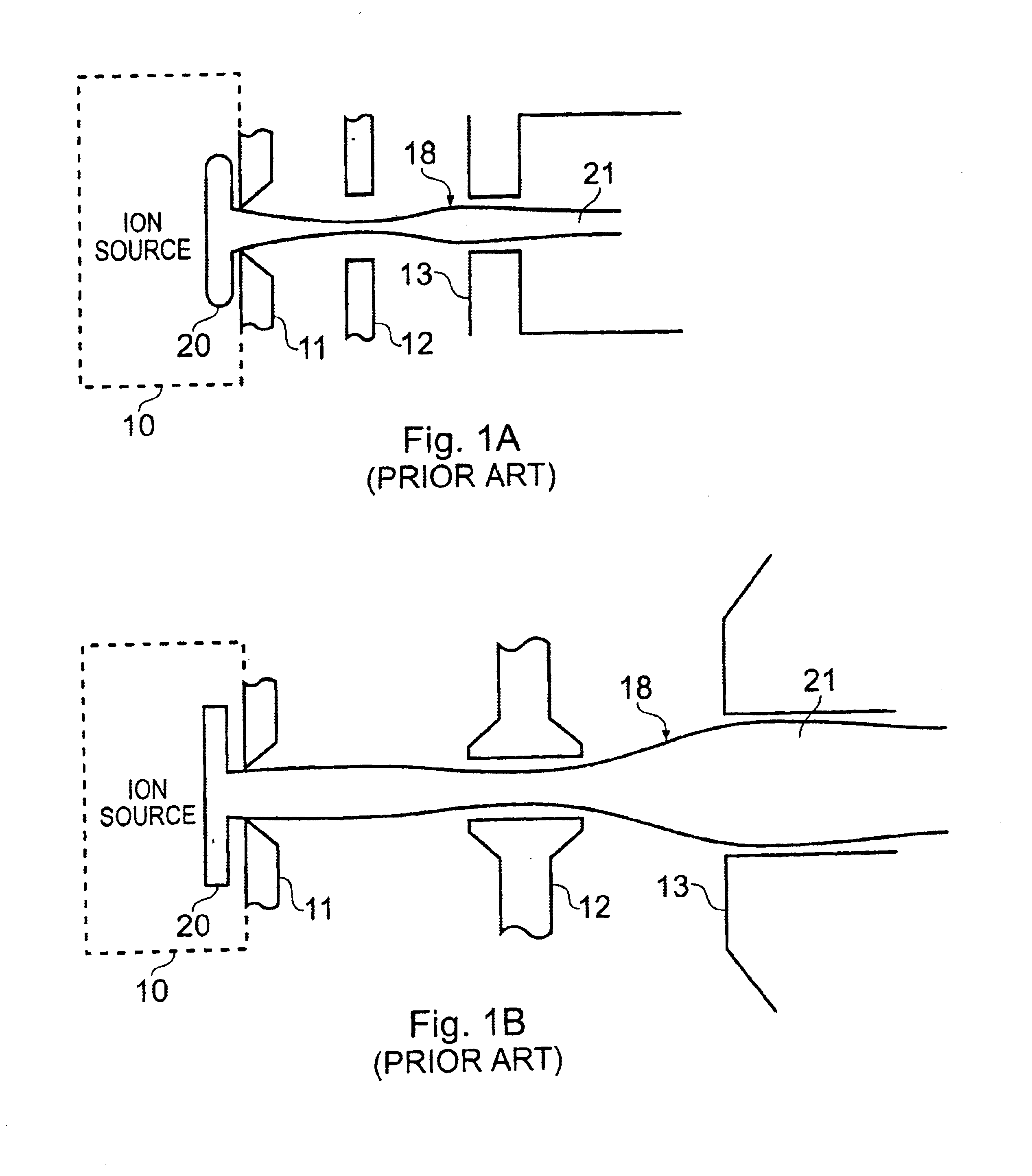
FIGS. 1A and 1B are schematic diagrams of prior art extraction systems. The extraction system of FIG. 1A is similar to a low energy commercial high current ion implantation system, and the extraction system of FIG. 1B is shown in the aforementioned paper by Hiroyuki Ito et al. Like elements in FIGS. 1A and 1B have the same reference numerals. An ion beam 18 is extracted from an ion source 10. Each extraction system includes a first electrode 11, an acceleration electrode 12 and a deceleration electrode 13. A plasma 20 is also shown. The plasma consists of electrons and positive ions. Also shown is a final beam plasma 21, which includes the final ion beam plus electrons and thermal positive ions.

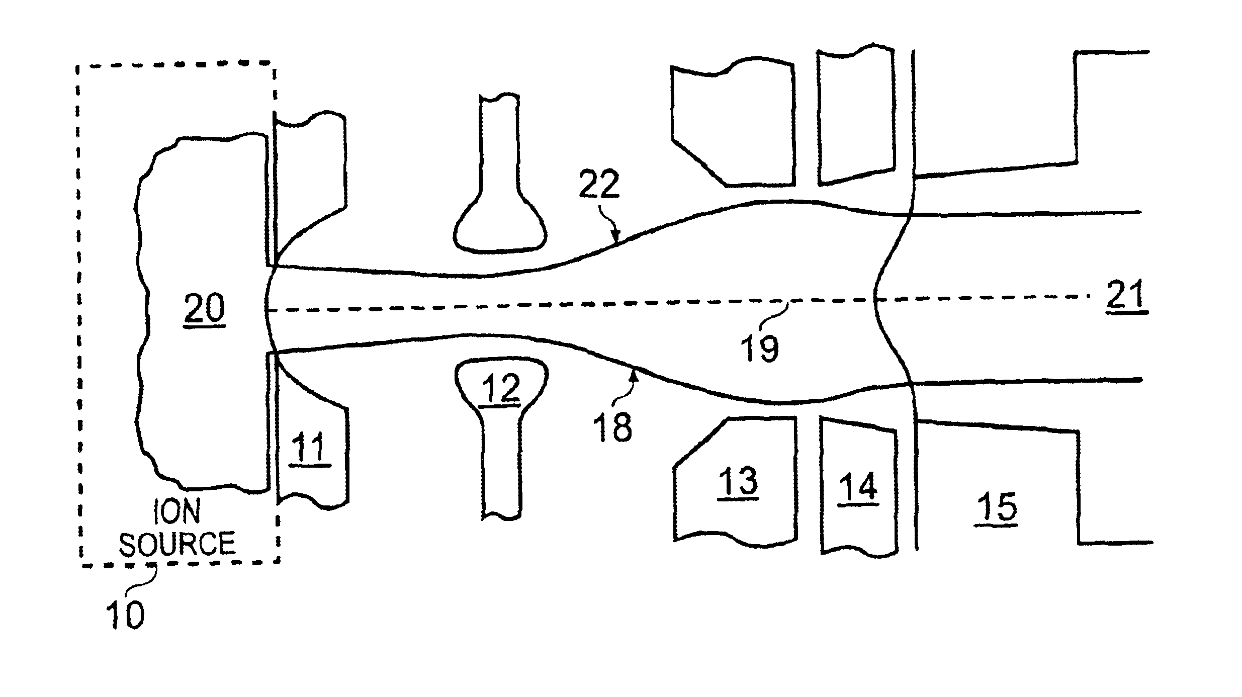
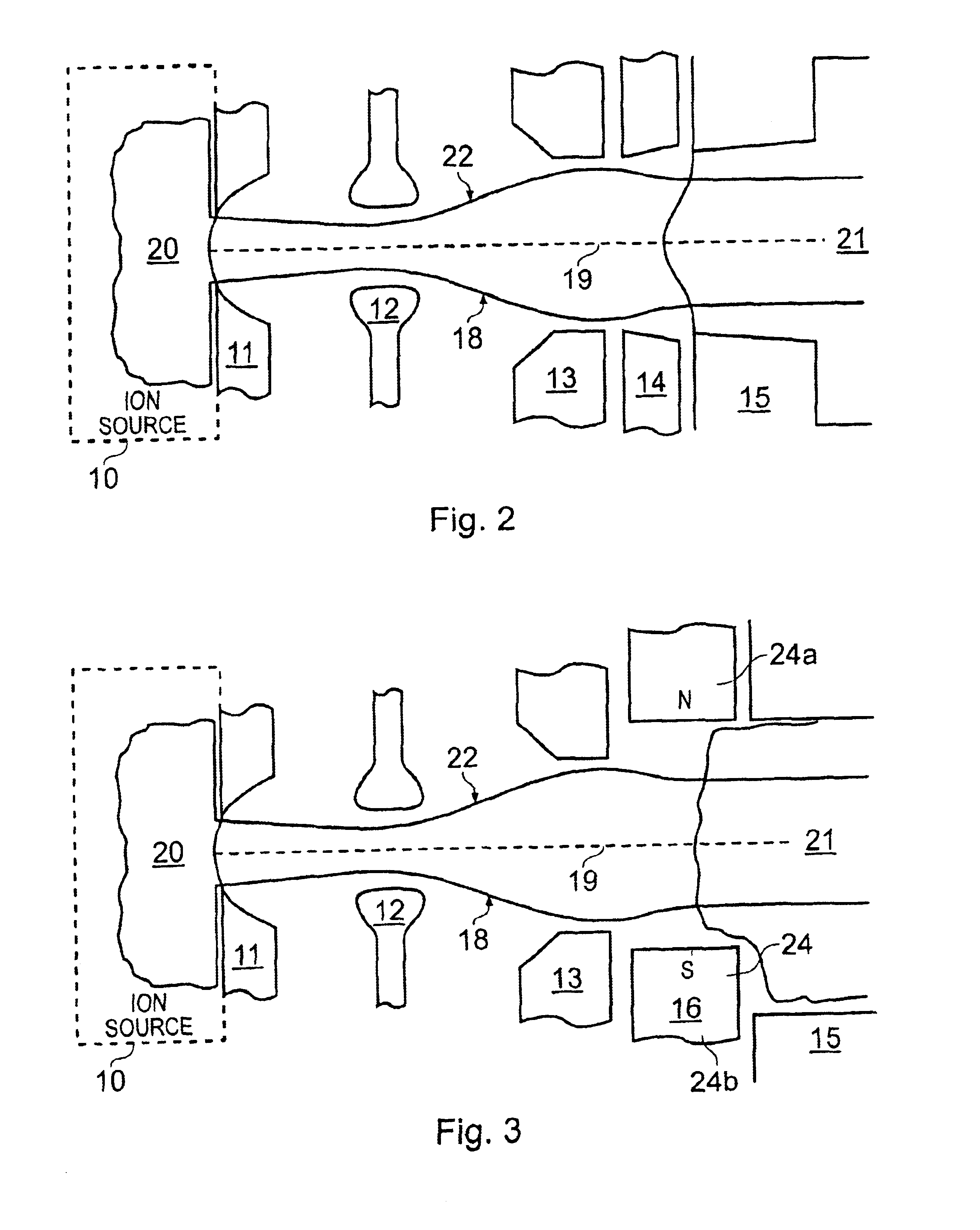
FIG. 2 is a schematic diagram of a low energy ion optical system in accordance with an embodiment of the invention. Like elements in FIGS. 1A, 1B and 2 have the same reference numerals. The system includes first electrode 11, acceleration electrode 12, deceleration electrode 13, an electron r...


PUM

PropertyMeasurementUnit
Ionizing radiationaaaaaaaaaa
Magnetic fieldaaaaaaaaaa
Densityaaaaaaaaaa

Abstract

Ion optical methods and apparatus are provided for producing low energy ion beams. The apparatus includes an acceleration electrode for accelerating the ion beam, a deceleration electrode downstream of the acceleration electrode for decelerating the ion beam, and an ion optical element downstream of the deceleration electrode for inhibiting electrons in the beam plasma from reaching the deceleration electrode. The deceleration electrode is biased at a voltage that is selected to provide a potential barrier to thermal ions in the beam plasma to inhibit the thermal ions from reaching the acceleration electrode. The ion optical element maybe implemented as an electron repulsing electrode or as a magnetic element. The acceleration electrode, the deceleration electrode, or both, may be segmented in a direction lateral to the ion beam to define individually controllable electrode segments. The ion optical apparatus may be implemented as an ion source extraction system or as a deceleration lens system.

Description

FIELD OF THE INVENTIONThis invention relates to ion beam systems such as ion implanters and, more particularly, to methods and apparatus for extraction and deceleration of low energy ion beams.BACKGROUND OF THE INVENTIONA number of systems are known for ion beam processing of a workpiece. Among these, ion implantation has become a standard technique for introducing conductivity-altering impurities into semiconductor wafers. A desired impurity material is ionized in an ion source, the ions are accelerated to form an ion beam of prescribed energy and the ion beam is directed at the surface of the wafer. The energetic ions in the beam penetrate into the bulk of the semiconductor material and are embedded into the crystalline lattice of the semiconductor material to form a region of desired conductivity.Ion implantation systems include an ion source for converting a gas or solid material into a well-defined ion beam. The ion beam is mass analyzed to eliminate undesired ion species, is a...

Claims


Application Information

Patent Timeline
IPC IPC(8): H01J37/08C23C14/48H01J37/317H01L21/265
CPCH01J37/08H01J2237/31701H01J37/30
Inventor KELLER, JOHN H.
Owner K2 KELLER CONSULTING
Why Eureka
Try Eureka