The
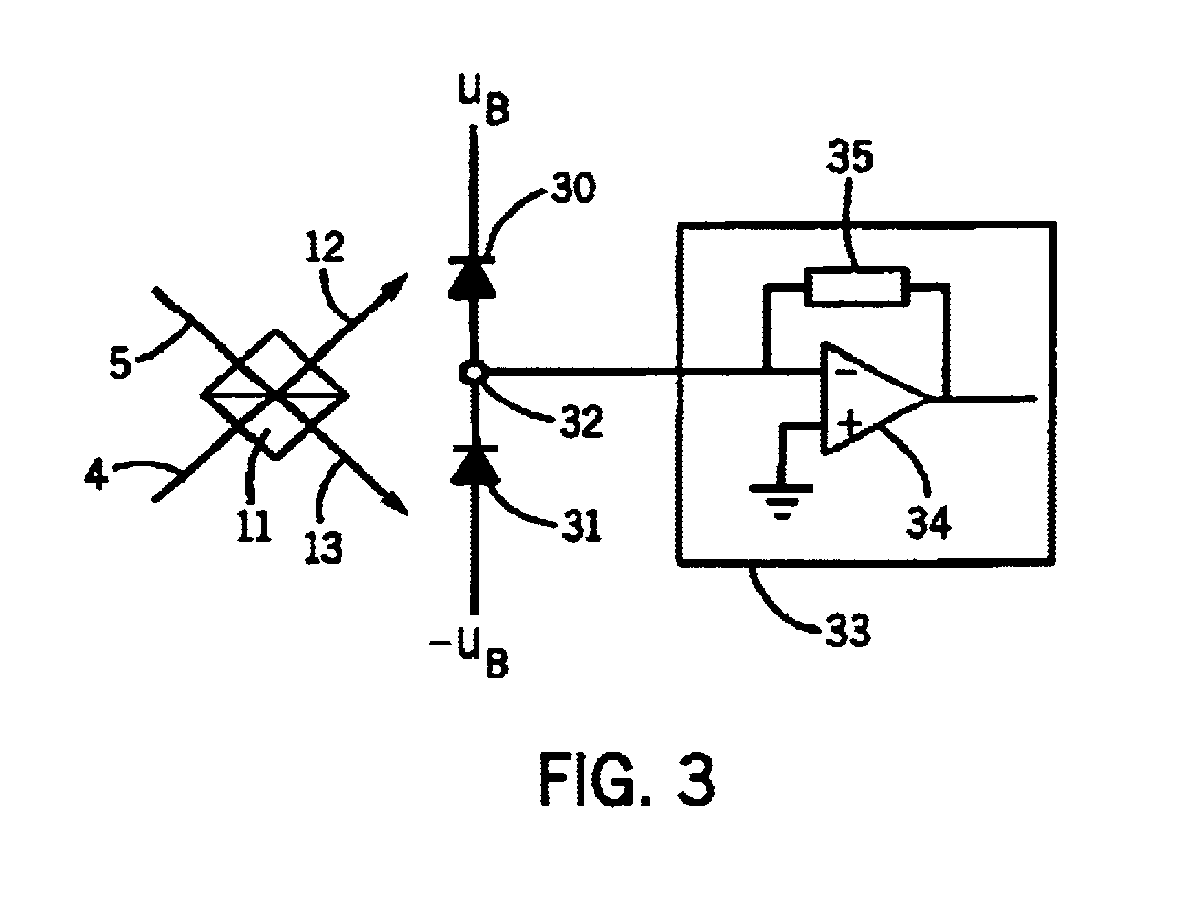
signal tappable between the optoelectronic transducers of the series connection and which in particular represents a difference between the photocurrents of two photodiodes of the series connection, is in a preferred embodiment supplied to an
amplifier circuit arrangement common to both transducers and which is preferably constructed as a transimpedance circuit. In the case of the detecting device according to the invention, for further processing the difference
signal it is consequently possible to use a single, suitable circuit arrangement. Compared with solutions based on two detectors, whereof each has a
transducer and an associated
amplifier circuit, this means a reduction in the number of components necessary, so that costs can be reduced and at the same time improves the precision of signal evaluation, because differences between several amplifier circuits resulting from component tolerances can be avoided when using a single amplifier circuit. The tap can in particular be connected in signal-conducting manner to an input of an
operational amplifier or another element acting in the same way.
According to a further development, the detecting device has a bias device for generating a substantially constant electric bias at the series connection in the
transducer blocking direction. As a result the
capacitance thereof can be reduced, which permits a low-noise signal generation even in the case of interferometers in which measurement information is transmitted in a
high frequency band, e.g. with
heterodyne interferometers operating e.g. with carrier frequencies of approximately 80 MHz.
The hitherto described measures contribute on the detection side to an improvement of the resolution of the
interferometry means down to the
quantum noise limit range. However, measures acting to improve resolution in the light generation range are also possible. As stated, in the case of heterodyne interferometers in order to permit measurements at the
quantum noise limit, it is necessary for the detection-side
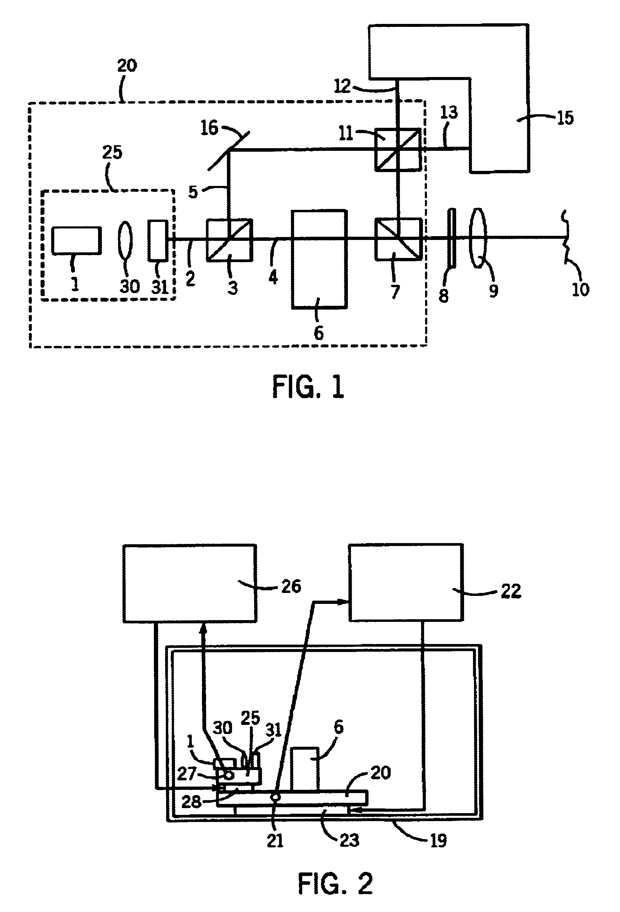
signal level to be higher than the level of the thermal noise of components of the detecting devices and in particular their load resistors. This can be achieved through a correspondingly high reference light power. The gas lasers frequently used nowadays, particularly in stationary equipment and research layouts become more expensive and larger with increasing power. In an advantageous further development a
laser diode constitutes the
light source.
Laser diodes are not only able to offer the desired high light powers of e.g. up to 1 mW, but are also inexpensively obtainable and are characterized by compact sizes. A particular
advantage for uses of the vibration measurements according to the invention in the medical sector and particularly in conjunction with operations, results from the fact that compared with gas lasers, laser diodes have very short warm-up times until the full power is reached and consequently the full measurement resolution is available.
As is known, the emission frequency of laser diodes is highly temperature-dependent, which can impair the measuring precision. So-called
mode hopping is the particular cause of this. In order to reduce temperature fluctuation-caused colour drift of the light source, according to a preferred development a multistage temperature stabilizing device is provided for stabilizing the light source temperature. The temperature stabilizing device has a thermostatted, first stabilizing unit heat-conductively connected to the light source and which is connected in
heat conducting manner with at least one thermostatted, second stabilizing unit. As a result, due to its
temperature control, the second stabilizing unit creates a relatively temperature-stable environment for the first stabilizing unit and the light source. Relative to this environment, which only has relatively small temperature fluctuations, the function of the first stabilizing unit is to further and more precisely stabilize the light source temperature. Multistage temperature stabilization, which can optionally have more than two stages, constitutes an inexpensive, constructional possibility of ensuring extremely stable light source temperatures without high
temperature control costs, which in turn leads to a
high frequency stability of the coherent light emitted. Attainable temperature fluctuations can be in the range well below 1 mK and e.g. between approximately 1 μK and approximately 10 to 20 μK.
For the further improvement of the
measurement precision, preferably at least one optical element for splitting and / or guiding the light of the light source is fitted together with said light source to a thermostatted stabilizing unit. It can in particular be a collimating
optics and / or an
optical isolator, i.e. a device preventing light being coupled back into the light source. Through the
joint temperature stabilizing the relative geometrical arrangement of said components with respect to one another remains largely insensitive to temperature influences. Alternatively or additionally it is possible for at least one optionally present
frequency shift device, particularly a Bragg
cell to be temperature-stabilized and for this purpose it can e.g. be fitted to one of the stabilizing units, particularly the second stabilizing unit. Thus, temperature influences on the frequency shift can be largely eliminated.
Devices according to the invention are preferably constructed as heterodyne interferometers. The frequency shift between the object light and the reference light necessary for
heterodyne interferometer operation can e.g. be obtained by tuning a
laser diode in conjunction with a
transit time difference between the measurement and difference light, i.e. in an unbalanced arrangement. Preferably the frequency shift device is constituted by an acousto-
optical modulator, particularly a Bragg
cell, which functions without movable components. In an embodiment a single frequency shift device is used, so that the structure is particularly inexpensive. Object light
phase modulation is also possible.

