Optical fiber and optical transmission line and optical communication system including such optical fiber

a technology of optical transmission line and optical fiber, which is applied in the direction of cladded optical fibre, instruments, optical elements, etc., can solve the problems of reducing the dispersion slope nz-dsf subject to limitations, limiting the wavelength band of pumping light for raman amplification, and almost unworkable in the s-band. , to achieve the effect of increasing the fwm generation efficiency, reducing the intensity of pumping light absorbed, and allowing

Inactive Publication Date: 2005-02-15
FURUKAWA ELECTRIC CO LTD
View PDF12 Cites 33 Cited by
  • Summary
  • Abstract
  • Description
  • Claims
  • Application Information

AI Technical Summary

Benefits of technology

According to Formulae 1 and 2, where a zero-dispersion wavelength of optical fiber interposes between signal lights S1−n and pumping lights R1−m, the FWM (F1−p) generation efficiency between the signal and pumping lights increases.
As described above, where the FWM F1−p occurs to degrade the transmission performance of signal lights S1−n, the increased FWM generation efficiency η results in an increase in the intensity of the pumping light absorbed by the FWM, thereby disallowing a large Raman gain for the signal lights.

Problems solved by technology

Yet, launching WDM signals into an optical fiber with too low chromatic dispersion induces unwanted waves in consequence of Four Wave Mixing (FWM), leading into a fault of the increase in the inter-channel cross talk.
However, even a reduced dispersion slope NZ-DSF is subject to limitations on its shorter-wavelength range by the zero dispersion wavelength, and on the longer-wavelength range by the cumulative dispersion.
In addition, the zero-dispersion wavelength of the NZ-DSF limits pump light wavelength band for the Raman amplification, almost unworkable in the S-band.

Method used


Image

  • Optical fiber and optical transmission line and optical communication system including such optical fiber
  • Optical fiber and optical transmission line and optical communication system including such optical fiber
  • Optical fiber and optical transmission line and optical communication system including such optical fiber

Examples


embodiment 1

[Embodiment 1]

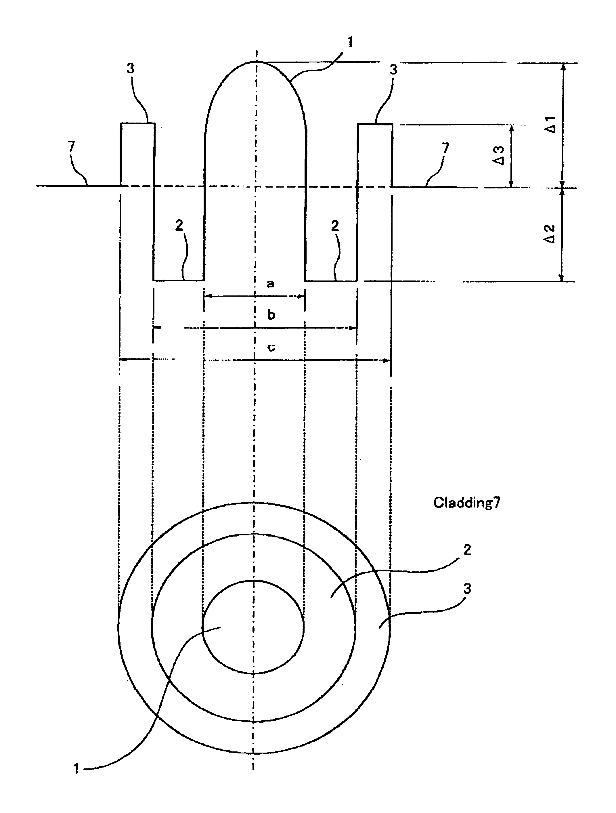
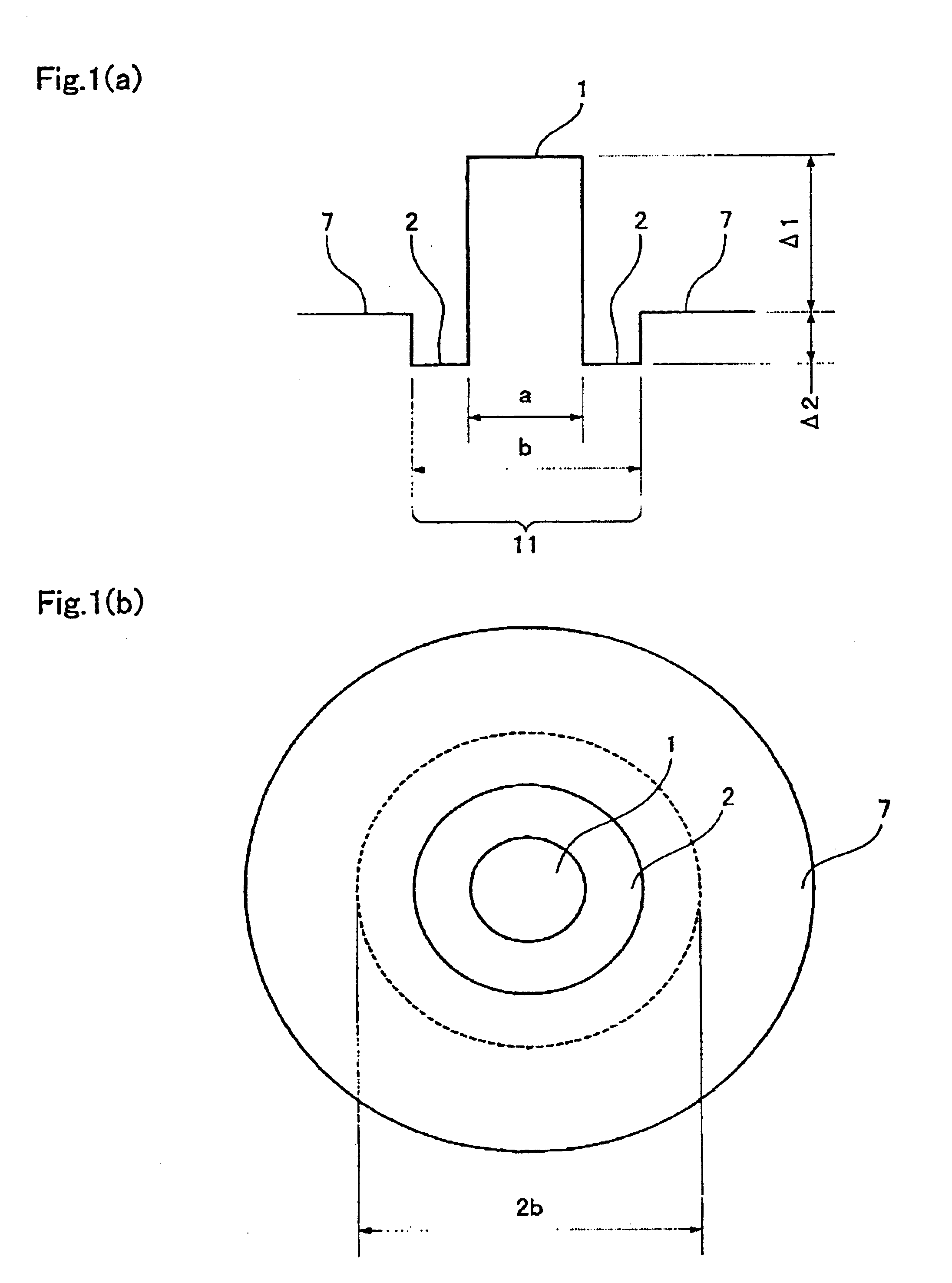
FIG. 1(a) shows a refractive index profile and FIG. 1(b) shows a cross-section of an optical fiber according to the first embodiment of the present invention. The refractive index profile in FIG. 1(a) features to be relatively simple and easy to design and control, compared to the other profiles.

Optical fiber of the first embodiment comprises of a core 11 at the center and a cladding 7 surrounding the core 11. In addition, the core has at least two layers with a first layer 1 at the center and a second layer 2 surrounding the first layer 1; the first layer 1 has a relative refractive index difference Δ1 of not less than 0.6% and not more than 1.6% with the cladding 7; the second layer has a relative refractive index difference Δ2 of negative value with the cladding 7; a diameter of the first layer 1 is shown as “a” and a diameter of the second layer 2 is shown as “b”.

The present patent specification defines the above relative refractive index differences (Δ1, Δ2, Δn) i...

first embodiment

The first embodiment allows a resultant optical transmission system with an average dispersion of not less than −10 ps / nm / km and not more than 1.0 ps / nm / km in a predetermined wavelength band of 1460 to 1625 nm, where the band may be partial or throughout between both wavelengths.

In addition to the above case with an optical fiber and an optical transmission system connected to a Raman amplified WDM transmission system, an optical fiber and an optical transmission system according to the first embodiment can be applicable for a WDM transmission system with other than Raman amplifier, for instance, one with EDFA (Erbium Doped Fiber Amplifier).

embodiment 2

[Embodiment 2]

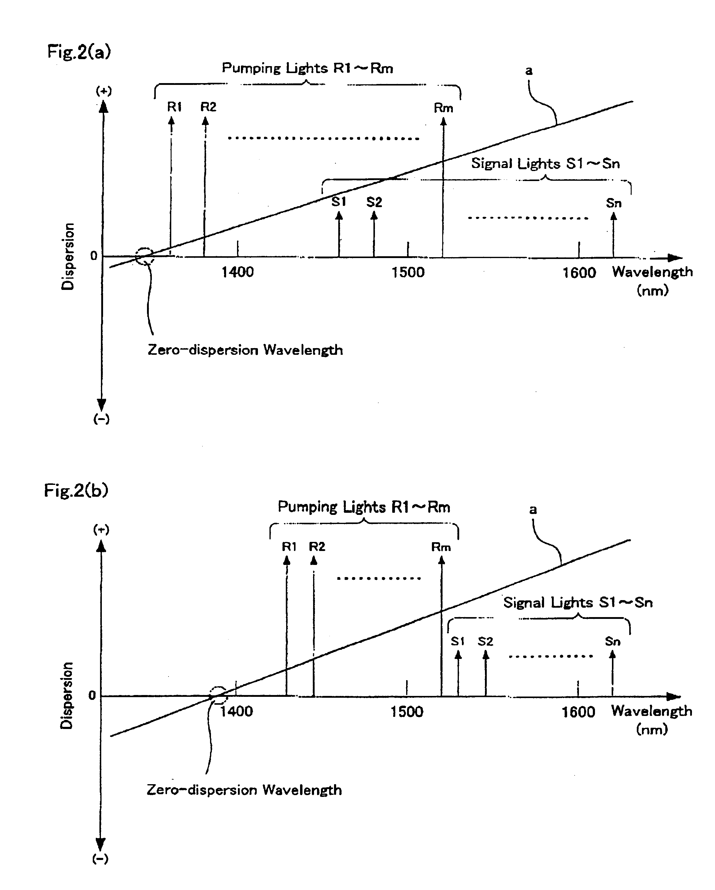
An optical fiber in a second embodiment has a zero dispersion wavelength of 1350 nm or shorter, and makes it possible to suppress the FWM and the cumulative dispersion over a broad wavelength band of 1400 to 1700 nm. The conventional reduced dispersion slope NZ-DSF proposed until now makes it possible to realize a signal transmission over the S, C and L-bands (1460-1625 nm). The optical fiber according to the second embodiment has a dispersion “D” of not less than 2 and not more than 8 ps / nm / km (2≦D≦8 ps / nm / km) even in the longer wavelengths of U-band (1625-1675 nm) and the shorter wavelengths of the E-band (1365-1700 nm), along with the referenced three bands, suppressing the FWM generation and the cumulative dispersion.

In the case when optical fibers in the second embodiment are applied to a transmission line, a distributed Raman amplifier, and a discrete Raman amplifier applied to at least one of the S, C and L-bands, can be combined to compensate the transmission l...


PUM


Abstract

Optical fibers to form an optical transmission line suitable for WDM transmission in a wide-spreading wavelength band, having the following characteristics and parameters: a dispersion in absolute value of 0.5 ps/nm/km to 9 ps/nm/km in a wavelength band of 1430 nm to 1625 nm, a dispersion slope in absolute value of 0.04 ps/nm2/km or less at a wavelength of 1550 nm, a mode field diameter of 7 μm or less at a wavelength of 1550 nm and a cable cutoff wavelength of less than 1430 nm; core 11 surrounded by cladding 7, core 11 being at least two-layered (first layer 1 at the center and second layer 2 surrounding the first layer; relative refractive index of glass layer Δ1 with reference to the cladding being adjusted to not less than 0.6 but not more than 1.6%, relative refractive index of second layer Δ2 with reference to the cladding being adjusted to a negative value.

Description

FIELD OF THE INVENTIONThe present invention relates to optical fiber suitable for wavelength division multiplexing (WDM) transmission, and optical transmission line, and optical communications system using such optical fibers.BACKGROUND OF THE INVENTIONThe volume of communication information data tends to greatly increase with the advancement of the information society necessitating the widespread use of wavelength division multiplexing (WDM) transmission in the field of telecommunications. WDM transmission enables to transmit optical signals of plurality of wavelengths through a single optical fiberThe erbium doped fiber amplifier (EDFA) is today developed and applied to amplify the optical signals at points of relay in a WDM transmission system. The EDFA does not require a process of transforming optical signals into electric signals at each wavelength, accelerating the spreading of WDM transmission worldwide.In the meantime, Raman amplifiers with the Raman amplification are of gr...

Claims


Application Information

Patent Timeline
Patent Type & Authority Patents(United States)
IPC IPC(8): G02B6/34
CPCH04B10/25253G02B6/02233G02B6/02238G02B6/02242G02B6/02271G02B6/03627G02B6/03644G02B6/03661G02B6/03677G02B6/03688G02B6/02028G02B6/02009G02B6/02285G02B6/0281G02B6/29376
Inventor KUMANO, NAOMI
Owner FURUKAWA ELECTRIC CO LTD
Why Eureka
Try Eureka