Patterning longitudinal magnetic recording media with ion implantation

a longitudinal magnetic recording and ion implantation technology, applied in the field of magnetic recording media, can solve the problems of requiring expensive servo-pattern writing equipment, and reducing the tribological performance of the disc assembly, so as to increase the recording density, and increase the coercivity of production

Inactive Publication Date: 2005-03-08
SEAGATE TECH LLC
View PDF21 Cites 64 Cited by
  • Summary
  • Abstract
  • Description
  • Claims
  • Application Information

AI Technical Summary

Benefits of technology

An advantage of the present invention is a magnetic recording medium having embedded servo-marks and increased areal recording density.
Another advantage of the present invention is a method of manufacturing a magnetic recording medium having topographically smooth servo information and increased areal recording density.
Additional advantages and other features of the invention will be set forth in the description which follows and in part will be apparent to those having ordinary skill in the art upon examination of the following or may be learned from the practice of the present invention. Advantages of the present invention may be realized and particularly pointed out in the appended claims.
According to the present invention, the foregoing and other advantages are achieved in part by a magnetic recording medium comprising: a magnetic layer having a substantially uniform surface containing a data zone and servo-information in the form of patterns. The servo-information comprises a distribution of high coercivity regions and a distribution of low coercivity regions that are capable of being sensed to enable positioning of a read / write head in the data zone, wherein the difference between the high coercivity regions and the low coercivity regions are from about 500 Oersted (Oe) to about 5000 Oe, e.g. about 800 Oe to about 2000 Oe.
Embodiments of the present invention include media where the servo-information comprises a series of regions extending in a radial direction across the data zone to divide the data zone into a plurality of sectors. The formed magnetic recording medium of the present invention allows reading from or writing on the magnetic recording medium by sensing, as by electrical means, one or more of the low coercivity regions making up the servo information on the magnetic recording medium; reading the magnetically recorded servo-information in a data track; and moving the read / write head to a particular position in the data zone in response to reading the servo-information.
A further aspect of the present invention is a method of patterning a magnetic layer having a high coercivity for the production of a magnetic recording medium. The method comprises exposing a selectively masked magnetic layer on a substrate to ions having an implantation energy of about 5 kiloelectron volts (KeV) to about 150 KeV to change the coercivity of the exposed magnetic layer without substantially affecting the topography of the magnetic layer to form a distribution of low coercivity regions functioning as servo-marks capable of being sensed by a read / write head. Advantageously, the present inventive patterning method allows the formation of servo information in a magnetic layer by creating low coercivity regions therein through ion implantation resulting in changing the coercivity of the exposed regions of the magnetic layer from about 500 Oe to about 5000 Oe.

Problems solved by technology

Because of the locational precision needed, writing of servo patterns requires expensive servo-pattern writing equipment and is a time consuming process.
While the depressions or voids formed in the disc are helpful in increasing track density, they tend to reduce the tribological performance of the disc assembly.
For example, during operation of the magnetic recording medium, the slider no longer travels over a smooth surface and thus causes several mechanical performance drawbacks.
These drawbacks include modulation of fly height when encountering servo patterns, fly height perturbations due to topography changes from the track width definition, glide defects from the stamping process, and disc distortion due to the servo patterning process.
However, it is believed that the use of such metal ions adversely damages the magnetic layer.

Method used


Image

  • Patterning longitudinal magnetic recording media with ion implantation
  • Patterning longitudinal magnetic recording media with ion implantation
  • Patterning longitudinal magnetic recording media with ion implantation

Examples


examples

A series of longitudinal magnetic recording media were subjected to ion implantation at selected energies and dosages. The media comprised a substrate, a 600 ÅNiAlT layer thereon, and a thin, e.g. 38 Å, CoMo seed layer on the nickel layer. A magnetic layer was deposited directly on the seed layer and comprised a CoCr layer, and two successive CoCrPtB layers thereon providing a total thickness of approximately 160 Å for the magnetic layers. Overlying the magnetic layer was an amorphous carbon overcoat of about 30 Å.

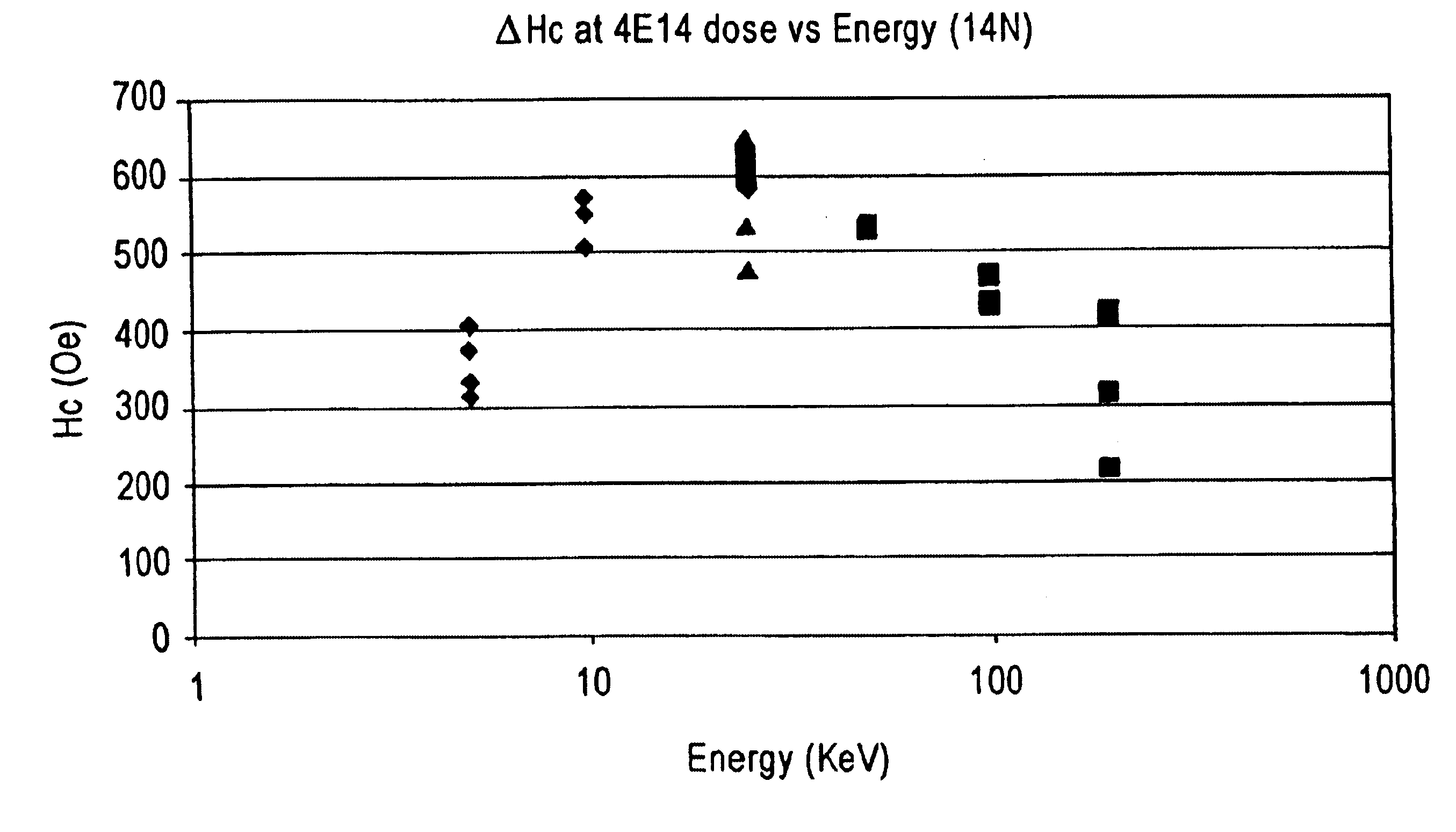
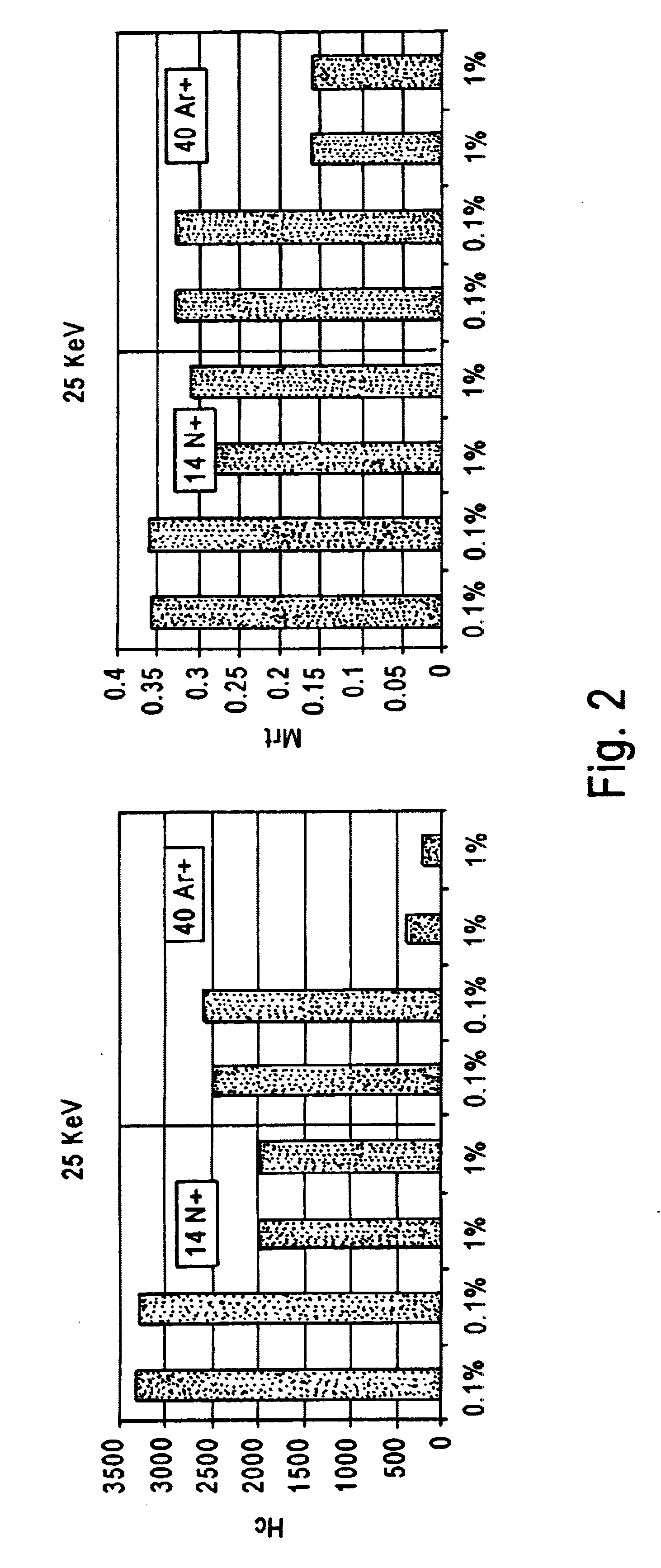
The magnetic layer had a coercivity of about 3950 Oe and an Mrt of about 0.4. FIG. 2 graphically illustrates the effect of implanting various dosages of either N+ or Ar+ions at 25 KeV through the carbon overcoat and through the magnetic layer. As shown, the coercivity was reduced from about 2500 Oe to as low as about 200 Oe and the Mrt was reduced from about 0.325 to about 0.17 with argon implantation. FIG. 3 graphically shows the effect on coercivity of the media by the c...


PUM

PropertyMeasurementUnit
magnetic fieldaaaaaaaaaa
sizeaaaaaaaaaa
coercivityaaaaaaaaaa

Abstract

A magnetic recording medium is formed with a distribution of low coercivity regions functioning as a transition pattern for servo information capable of being sensed by a read/write head by exposing a masked magnetic layer to ions to change the coercivity of the exposed magnetic layer without substantially affecting the topography of the magnetic layer.
Embodiments of the present invention include forming a series of substantially radially extending low coercivity regions used to divide the magnetic layer into a plurality of sectors comprising substantially concentric circumferentially extending data tracks by exposing a masked magnetic layer having a high coercivity, i.e. from about 2000 Oe to about 10000 Oe, to one or more heavy atom ion bombardments of gaseous ions, e.g. argon ions, at a dose of about 1×10¹³ atoms/cm2 to about 9×10¹⁵ atoms/cm2 having an implantation energy of about 10 KeV to about 50 KeV.

Description

FIELD OF THE INVENTIONThe present invention relates to magnetic recording media containing substantially radially distributed servo-marks and to a method for manufacturing the magnetic recording media. The present invention has particular applicability in forming servo-marks for use in high areal recording density magnetic recording media with increased data reading speed.BACKGROUND ARTThin film magnetic recording discs and disc drives are conventionally employed for storing large amounts of data in magnetizable form. In operation, a typical contact start / stop (CSS) method involves a floating transducer head gliding at a predetermined distance from the surface of the disc due to dynamic pressure effects caused by air flow generated between the sliding surfaces of the transducer head and the disc. During reading and recording (writing) operations, the transducer head is maintained at a controlled distance from the recording surface, supported on a bearing of air as the disc rotates, ...

Claims


Application Information

Patent Timeline
Patent Type & Authority Patents(United States)
IPC IPC(8): C23C14/48C23C14/04G11B5/855G11B5/82G11B5/74
CPCB82Y10/00C23C14/042C23C14/48G11B5/855G11B5/743G11B5/82G11B5/74
Inventor KUO, DAVIDLI, XINWEIGUI, JING
Owner SEAGATE TECH LLC
Why Eureka
Try Eureka