Semiconductor integrated circuit device and method of manufacturing the same
a technology of integrated circuit and semiconductor, which is applied in the direction of semiconductor devices, diodes, electrical apparatus, etc., can solve the problems of gate oxide film not being able to provide stable capacitance and noticeably increasing leakage current, so as to reduce leakage current of capacitive elements constituted by misfet, high threshold voltage, and operation reliably
- Summary
- Abstract
- Description
- Claims
- Application Information
AI Technical Summary
Benefits of technology
Problems solved by technology
Method used
Image
Examples
embodiment 1
(Embodiment 1)
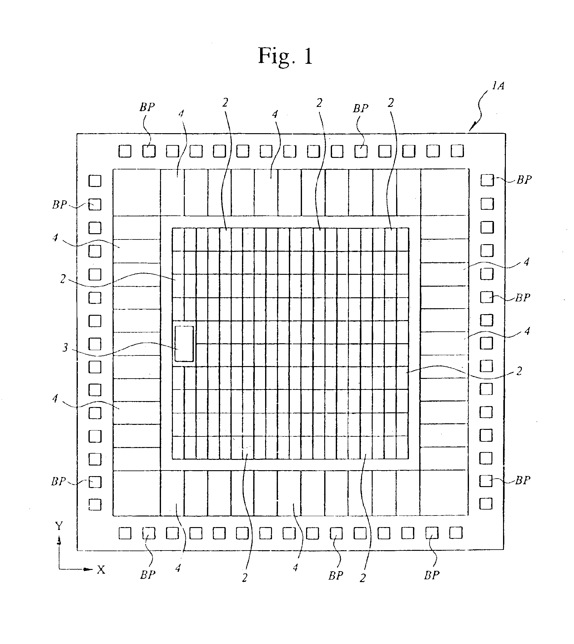
The semiconductor integrated circuit according to Embodiment 1 is a CMOS (Complementary Metal Oxide Semiconductor) gate array. FIG. 1 shows the semiconductor chip IA incorporating the CMOS gate array.
As shown in FIG. 1, a number of fundamental cells 2 constituting the logic section of the CMOS gate array are arranged on the center part of the major surface of the semiconductor chip 1A made of single crystal silicon. More specifically, the cells 2 are arranged in rows (in X direction) and columns (in Y direction), forming a matrix: Each fundamental cell 2 is composed of n-channel MISFETs Qn1 (not shown) and p-channel MISFETs Qp1 (not shown). The MISFETs Qn1, and Qp1 are connected in each cell 2, and the cells 2 are connected to each other based on a logical design. Therefore, the CMOS gate array performs desired logic operations.
The connection for performing the above logic operations are made by means of a DA (Design Automation) system that employs, for example, CAD (C...
embodiment 2
(Embodiment 2)
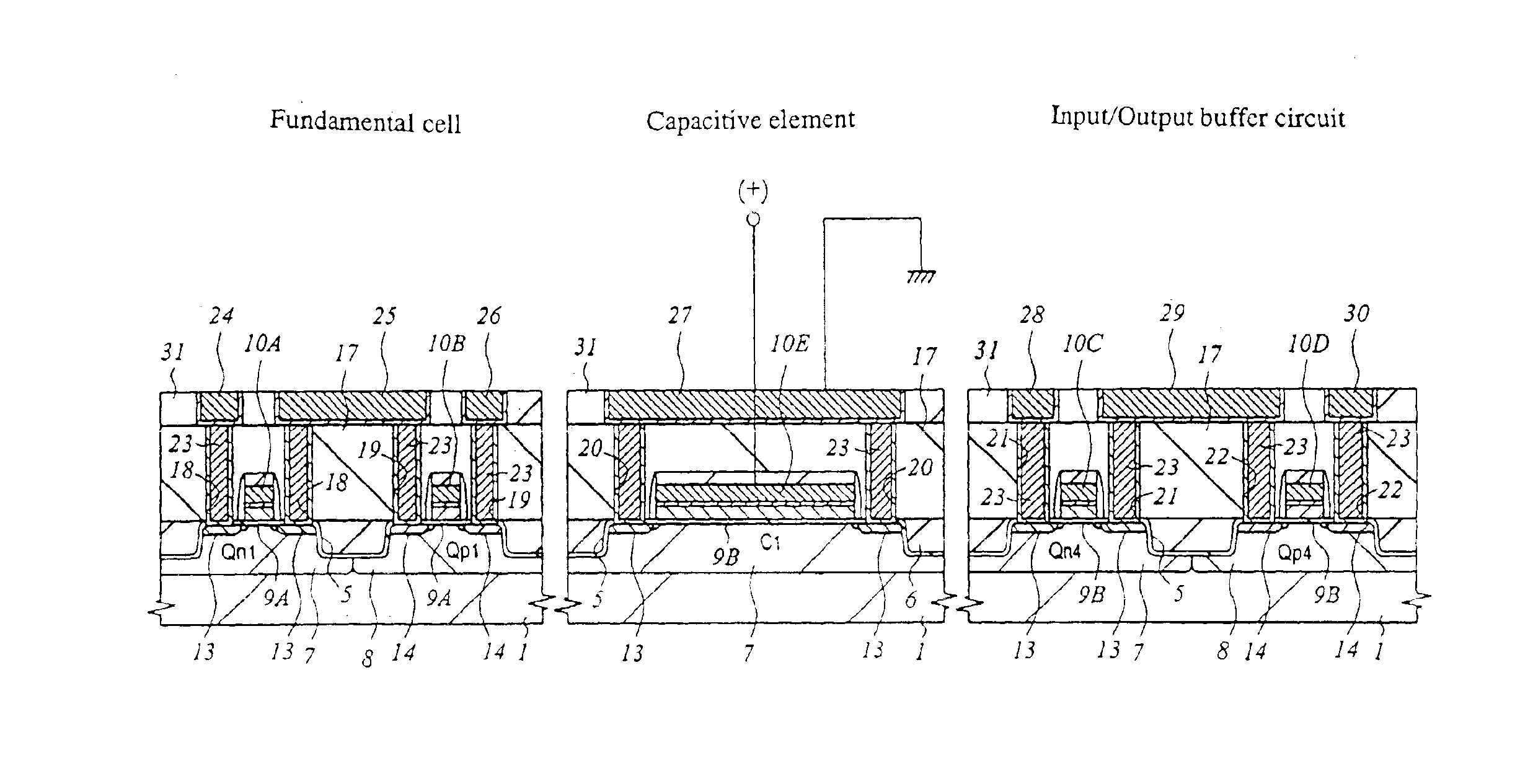
The capacitive element C1 provided in the PLL circuit 3 may comprise such an n-channel MISFET as illustrated in FIG. 20. The capacitive element C1 shown in FIG. 20 is formed in a p-type well 7 of a substrate 1. This capacitive element C1 is composed of mainly a gate oxide film 9B, a gate electrode 10E, and n-type semiconductor region 13.
The oxide film 9B of the capacitive element C1 is as thick as the gate oxide films 9B of MISFETs (Qn4, Qp4) constituting an input / output buffer circuit 4. That is, it is, for example, about 6.5 nm thick. The p-type well 7 is doped with n-type impurities (e.g., As) so that the n-channel MISFETs have a lower threshold voltage than the other n-channel MISFET Qn4. Hence, the capacitive element C1 can reliably operate even at a low power-supply voltage.
FIG. 21 is a graph illustrating the Vg-C characteristic of the capacitive element C1 comprising an n-channel MISFET.
As described above, the capacitive element C1 has the oxide film 9B that is ...
embodiment 3
(Embodiment 3)
Embodiments 1 and 2 described above are CMOS gate arrays. Nevertheless, the present invention can be applied to such an LSI of standard-cell system as shown in FIG. 26, designed for a particular use and having macro cells such a logic block, a DRAM (Dynamic Random Access Memory) and a SRAM (Static Random Access Memory). In this case, too, the capacitive elements incorporated in an analog PLL circuit may have gate oxide films 9B that are as thick as the gate oxide films of the MISFETs that constitute an input / output buffer circuit 4 and the gate oxide films of the MISFETs QM and QS that constitute the memory cells of the DRAM and SRAM. Thus, the same advantages can be attained as in Embodiment 1.
The present invention can be applied to not only gate arrays and standard cells, but also to various types of LSIs, such as a microcomputer, which has circuits each composed of two or more kinds of MISFETs that differ in the thickness of gate oxide film. In the case of a microco...
PUM
 Abstract
Description
Claims
Application Information
 - R&D
- Intellectual Property
- Life Sciences
- Materials
- Tech Scout
- Unparalleled Data Quality
- Higher Quality Content
- 60% Fewer Hallucinations
Browse by: Latest US Patents, China's latest patents, Technical Efficacy Thesaurus, Application Domain, Technology Topic, Popular Technical Reports.
© 2025 PatSnap. All rights reserved.Legal|Privacy policy|Modern Slavery Act Transparency Statement|Sitemap|About US| Contact US: help@patsnap.com


