

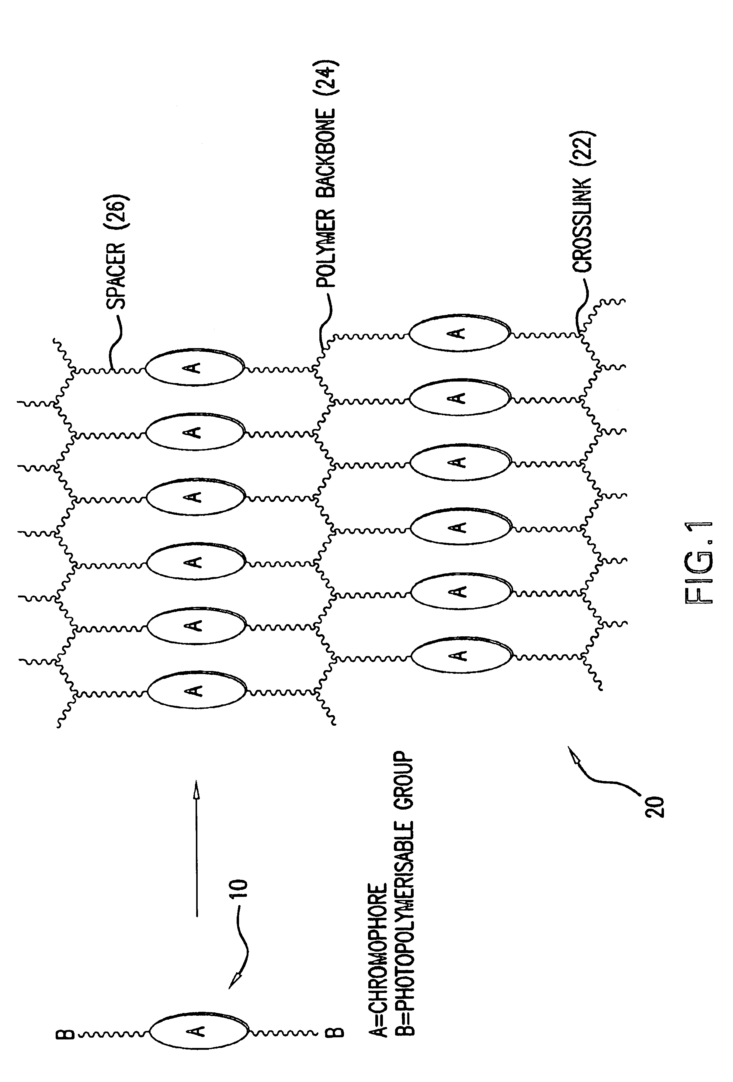
Light emitting polymer
a light-emitting polymer and polymer technology, applied in the field of polymerisation process, can solve the problems of heavy power drain and low external transmission efficiency of 4%
- Summary
- Abstract
- Description
- Claims
- Application Information
AI Technical Summary
Benefits of technology
Problems solved by technology
Method used
Image

Examples
Embodiment Construction
General Experimental Details
Fluorene, 2-(tributylstanyl)thiophene, 4-(methoxyphenyl)boronic acid and the dienes were purchased from Aldrich and used as received. Reagent grade solvents were dried and purified as follows. N,N-Dimethylformamide (DMF) was dried over anhydrous P2O5 and purified by distillation. Butanone and methanol were distilled and stored over 5 Å molecular sieves. Triethylamine was distilled over potassium hydroxide pellets and then stored over 5 Å molecular sieves. Dichloromethane was dried by distillation over phosphorus pentoxide and then stored over 5 Å molecular sieves. Chloroform was alumina-filtered to remove any residual ethanol and then stored over 5 Å molecular sieves. 1H nuclear magnetic resonance (NMR) spectra were obtained using a JOEL JMN-GX270 FT nuclear resonance spectrometer. Infra-red (IR) spectra were recorded using a Perkin Elmer 783 infra-red spectrophotometer. Mass spectral data were obtained using a Finnegan MAT 1020 automated GC / MS. The purit...
PUM
| Property | Measurement | Unit |
|---|---|---|
| organic chain | aaaaa | aaaaa |
| temperature | aaaaa | aaaaa |
| electroluminescence | aaaaa | aaaaa |
Abstract
Description
Claims
Application Information