Process for the catalytic oxidation of hydrocarbons

a hydrocarbon and catalytic oxidation technology, applied in the direction of hydrocarbons, hydrocarbon cracking, chemical/physical processes, etc., can solve the problems of unstable reaction, reduced selectivity, and non-uniform velocity profile of reactant mixture, so as to improve mixing and/or velocity profile of reactants, improve the effect of mixing and/or mixing

Inactive Publication Date: 2005-04-19
INEOS EURO LTD +1
View PDF7 Cites 0 Cited by
  • Summary
  • Abstract
  • Description
  • Claims
  • Application Information

AI Technical Summary

Benefits of technology

[0020]Advantageously, improved mixing and/or improved velocity profile of the reactants may be achieved by passing the reactant mixture through a baffle zone prior to entry into the heat exchanger.
[0021]Thus, in another aspect of the invention, the hydrocarbon and oxygen-containing gas are mixed in at least one baffle zone, prior to being passed through the heat exchanger. The baffle zone is defined by a housing, which contains at least one baffle plate. By baffle plate is

Problems solved by technology

However, although the reactants (hydrocarbon and oxygen-containing gas) may be pre-mixed prior to being introduced into the reactor, the velocity profile of the reactant mixture is often still nonuniform.
Such a non-uniform velocity profile can lead to an unstable reaction.
For example, high velocity gas mixtures over only part of the catalyst can lead to a decrease in selectivity.
Where the oxidation

Method used


Image

  • Process for the catalytic oxidation of hydrocarbons

Examples


example 1

[0087]In this Example, ethane, oxygen and hydrogen were utilised as feed in the general reaction method above. The reactant mixture was pre-heated to a temperature below the autoignition temperature of the mixture. The results are shown in Table 1 below.

example 2

[0088]The data in this Example was obtained by thermochemical analysis of the data in Example 1. The preheat temperature of the reactant mixture was set at a temperature above its autoignition temperature. The results are shown in Table 1 below.

[0089]

TABLE 1Example 1Example 2Preheat Temperature ° C.195450Ethane:Oxygen ratio2.433.08Hydrogen:Oxygen ratio0.120.12Feed velocity at catalyst5.477.43face at preheat temperaturem / sEthane conversion %69.1468.71Ethylene selectivity72.2973.74(g / 100 g C2 converted)Carbon monoxide15.2812.13selectivity(g / 100 g C2 converted)Carbon dioxide selectivity2.011.59(g / 100 g C2 converted)Methane selectivity8.578.74(g / 100 g C2 converted)Acetylene selectivity0.590.60(g / 100 g C2 converted)C3 selectivity2.162.19(g / 100 g C2 converted)C4 selectivity2.02.1(g / 100 g C2 converted)C5+ selectivity0.380.38(g / 100 g C2 converted)

[0090]It is expected and believed that in the absence of the heat exchanger and / or bafie zone, the conversion of ethane and / or selectivity to ethy...

example 3

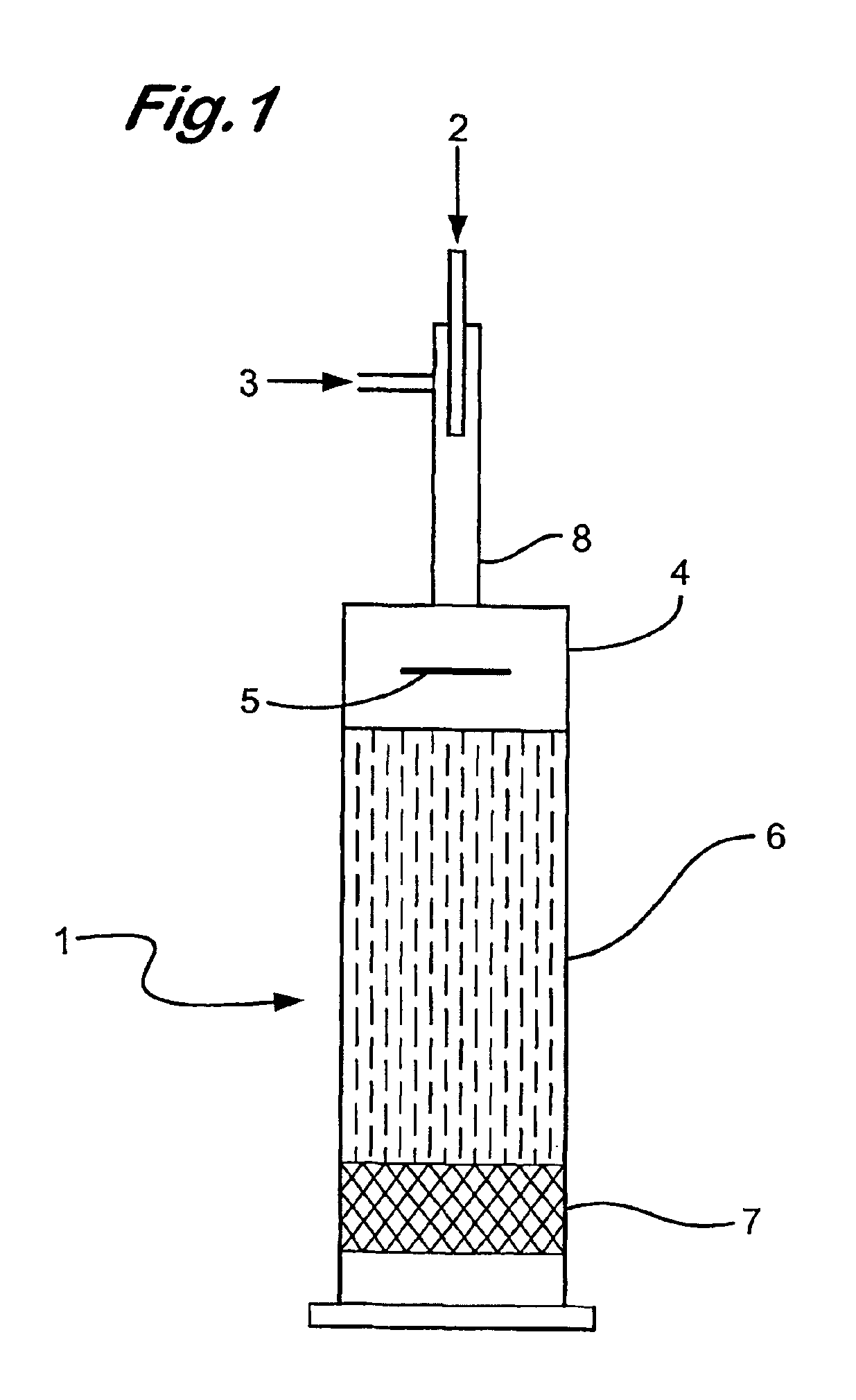
[0092]Using the apparatus as described in FIG. 1, the distribution of oxygen in an oxygen / ethane gas mixture (ratio of oxygen to ethane, 1:2.4) fed into the baffle zone (4) by the injector (8), passing through the baffle zone (4) and into the compact heat exchanger (6) was analysed by 3D CFD modelling using Fluent™ software. In this Example the baffle plate (5) was disposed perpendicularly i.e at 90 degrees to the oxygen / ethane gas flow.

[0093]The CFD modelling results demonstrated that the oxygen and ethane partially mix in the injector (8) prior to entry into the baffle zone (4). After deflection by the baffle plate (5) the oxygen and ethane gases appear to be substantially mixed (approximately 99% mixed)

[0094]No further mixing of the gases was observed after exit from the baffle zone (4).


PUM

PropertyMeasurementUnit
Temperatureaaaaaaaaaa
Lengthaaaaaaaaaa

Abstract

A process for the production of an olefin comprising partially combusting in a reaction zone a mixture of a hydrocabon and an oxygen-containing gas in the presence of a catalyst which is capable of supporting combustion beyond the fuel rich limit of flammability to produce the olefin. Prior the partial combustion, the mixture of the hydrocabon and the oxygen-containg gas is passed through a heat excahanger, and the heat exchanger provides a pressure drop.

Description

[0001]The present invention relates, in general, to the catalytic oxidation of hydrocarbons and, in particular, to the catalytic oxidative dehydrogenation of hydrocarbons to produce olefins.BACKGROUND OF THE INVENTION[0002]Processes for the catalytic oxidation of hydrocarbons are well known, for example, the oxidation of methane to produce syngas; the oxidation of ethylene to produce ethylene oxide; the oxidation of ethylene and acetic acid to produce vinyl acetate; the production of maleic anhydride from the oxidation of butene, butane or benzene; the production of phthalic anhydride by the oxidation of naphthalene or o-xylene; the ammoxidation of propane to acrylonitrile.[0003]The catalytic oxidative dehydrogenation of hydrocarbons is a known process for the production of olefins. An example of such a process is described in EP-A-0 332 289. In this process, a hydrocarbon and an oxygen-containing gas are contacted with a catalyst, which is capable of supporting combustion beyond th...

Claims


Application Information

Patent Timeline
IPC IPC(8): B01J19/26B01J8/02B01J19/00C07C253/00C07C253/24C07C5/48C07C51/16C07C5/00C07D301/00C07C45/00C07C51/265C07C51/31C07D301/08C07C51/215C07C67/00C07C67/05C07C45/33C01B3/38C07D307/60C07B61/00C07C5/333C07C11/04C07C69/15C07D307/89
CPCB01J8/0242B01J8/0285C07D301/08C07C253/24C07C67/05C07C51/313C07C51/265C07C51/215C07C45/33C07C5/48C01B3/386B01J19/006B01J19/26C07C11/02C07C57/145C07C63/16C07C69/01C07C69/15C07C255/08C01B2203/1288C01B2203/1247C01B2203/107C01B2203/1058C01B2203/1047C01B2203/0261B01J2208/00B01J2219/00069B01J2219/00085B01J2219/00155B01J2219/00159B01J2219/00164B01J2219/00243B01J2219/0286B01J2219/1923
Inventor COLMAN, DEREK ALANHESKETH, TREVOR JOHNREID, IAN ALLAN BEATTIEWOODFIN, WILLIAM TERENCE
Owner INEOS EURO LTD
Why Eureka
Try Eureka