

Lighting equipment
a technology of light equipment and equipment, which is applied in the direction of vehicle headlamps, synthetic resin layered products, spectral modifiers, etc., can solve the problems of easy breakage of reflectors, difficult work of metal into complicated shapes such as vehicular extension reflectors, and difficult handling of metal, etc., to achieve superior surface smoothness, heat resistance, moldability, and reflection characteristics.
- Summary
- Abstract
- Description
- Claims
- Application Information
AI Technical Summary
Benefits of technology
Problems solved by technology
Method used
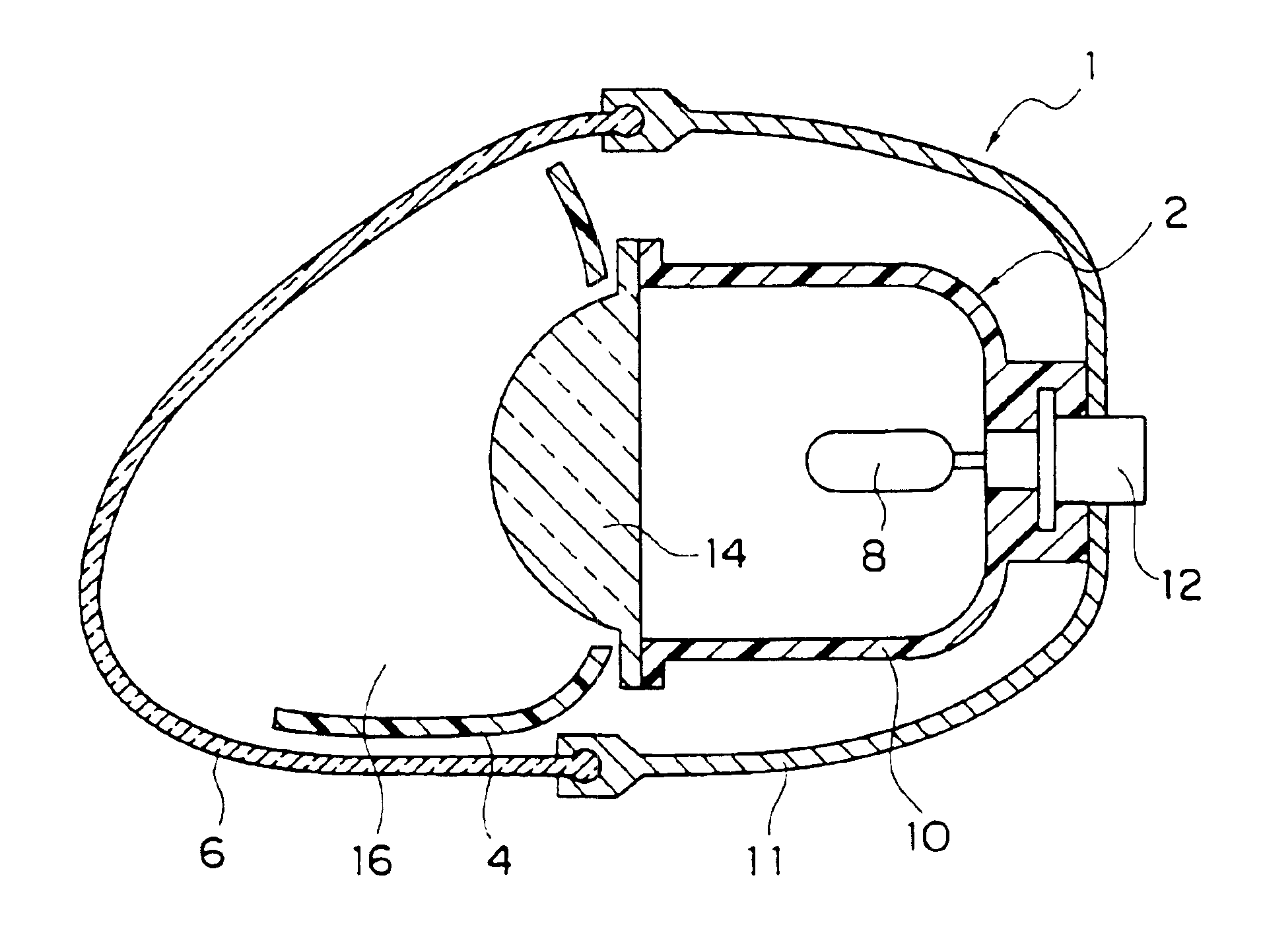
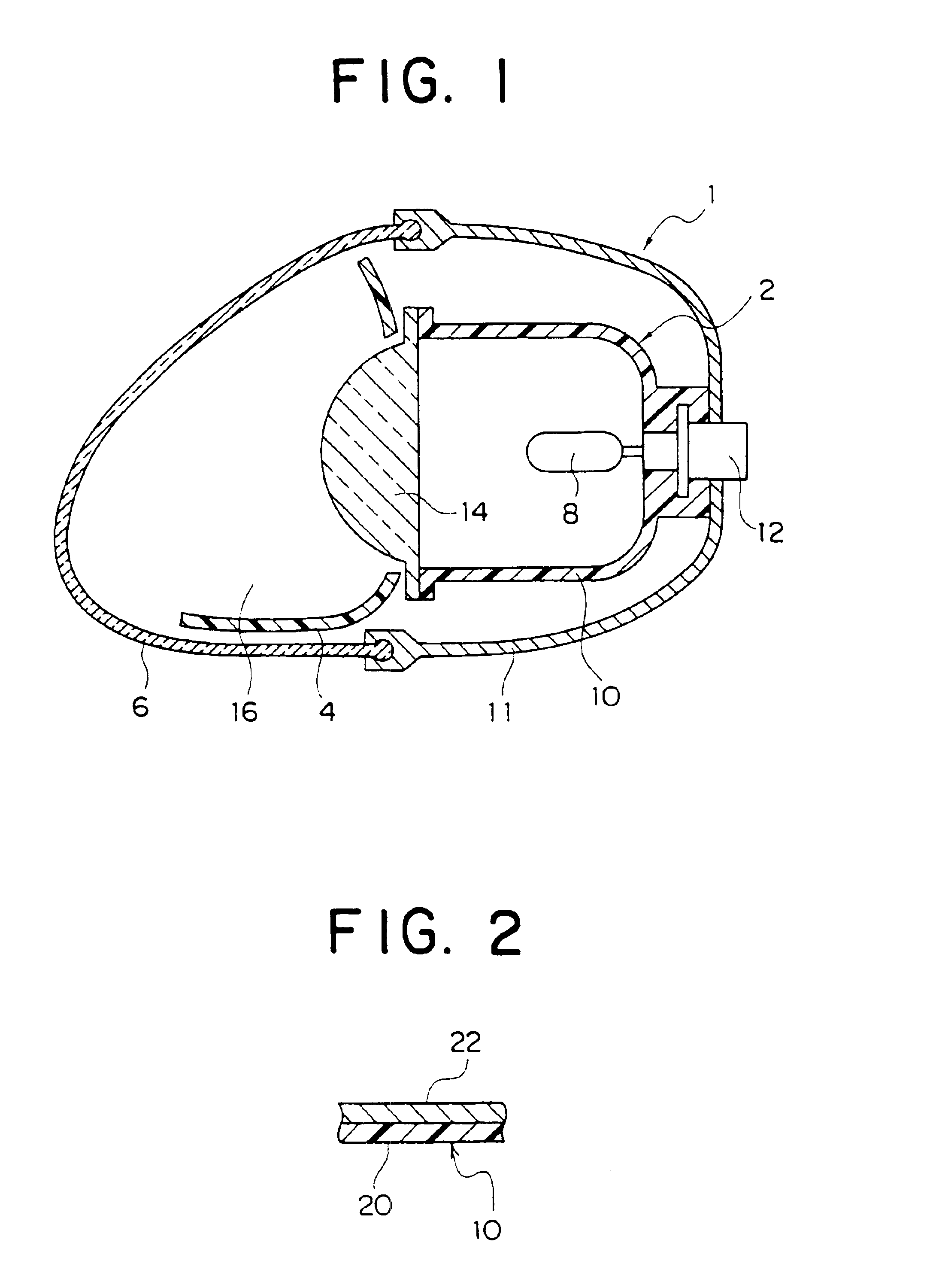
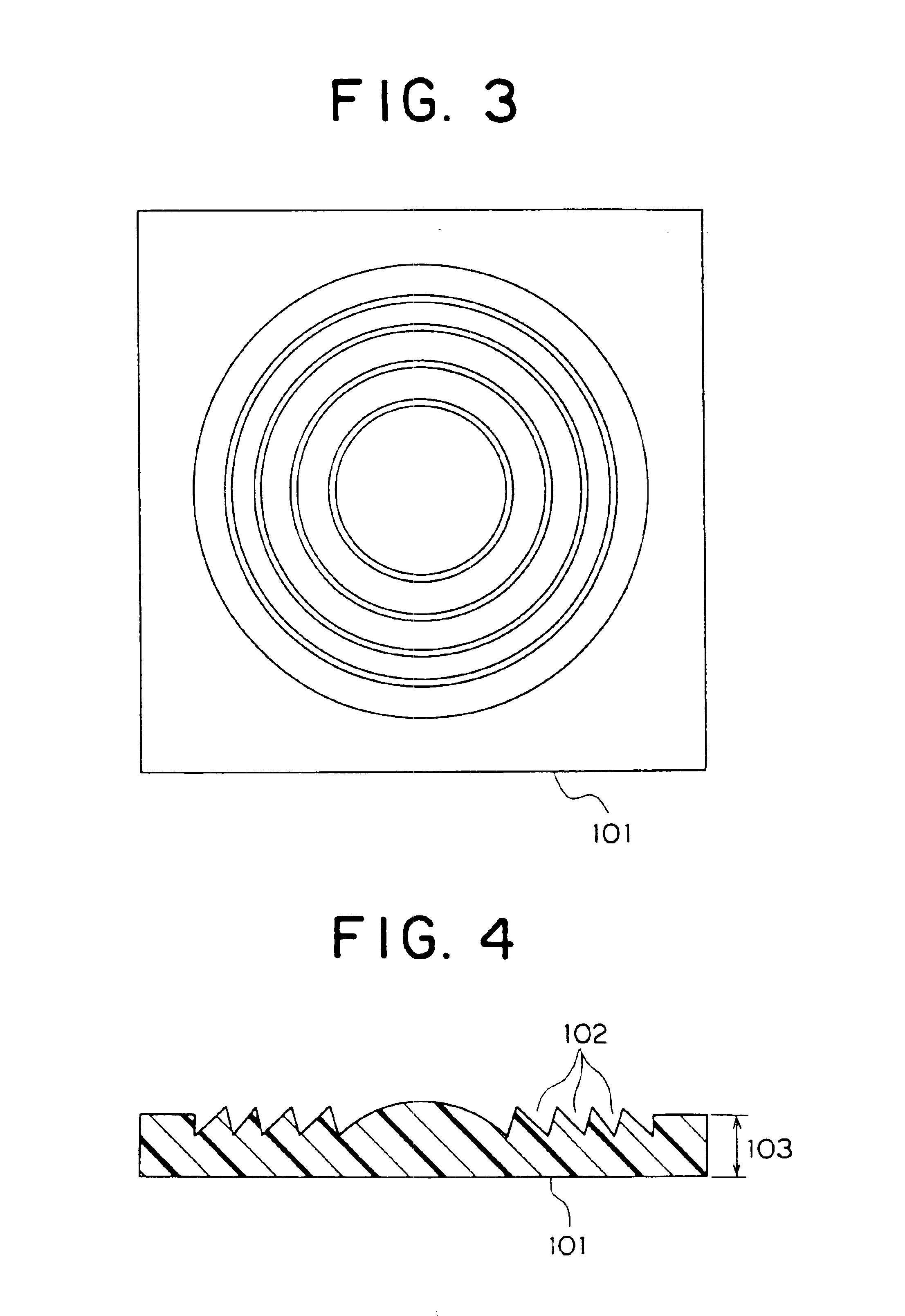
Image

Examples
production example 1
[0295]400 parts of dehydrated toluene, 0.68 part of 1-hexene, 0.25 part of isopropyl ether, 0.18 part of isobutyl alcohol, 0.48 part of isobutyl aluminum, and 42 parts of a 0.77% toluene solution of tungsten hexachloride were charged into a polymerization reactor and mixed at room temperature in a nitrogen atmosphere, then 120 parts of 1,4-methano-1,4,4a,9a-tetrahydrofluorene (hereinafter also referred to as MTF), 80 parts of tetracyclo[4.4.0.12,5.17,10]dodeca-3-ene (hereinafter also referred to as tetracyclododecene or TCD), and 25 parts of a 0.77% toluene solution of tungsten hexachloride were continuously added at 45° C. over 2 hours for the polymerization.
[0296]300 parts of the polymerization reaction solution was transferred to an autoclave equipped with a stirrer, then 9 parts of an alumina-carried nickel catalyst was added and a reaction caused at 190° C. and 45 kgf / cm2 for 8 hours. The solution was filtered by filter paper with a pore size of 1 μm using diatomaceous earth as...
production example 3
[0302]A cyclohexane solution of tetracyclododecene (TCD) was continuously supplied from the top of a 1 m3 polymerization reactor provided with a stirrer to give a concentration of supplied TCD in the polymerization reactor of 60 kg / m3. As the catalyst, a cyclohexane-based solution of VO(O—C2H5)Cl2 was continuously supplied into the polymerization reactor from the top of the polymerization reactor to give a concentration of vanadium in the polymerization reactor of 0.9 mol / m3 and a cyclohexane solution of ethyl aluminum sesquichloride (Al(C2H5)1.5Cl1.5) was continuously supplied to give a concentration of aluminum in the polymerization reactor of 7.2 mol / m3. Further, the polymerization system was supplied with ethylene at a rate of 85 m3 / hour, nitrogen at a rate of 45 m3 / hour, and hydrogen at a rate of 6 m3 / hour using a bubbling tube.
[0303]A copolymerization reaction was performed while holding the polymerization system, comprised of the polymerization reactor, a jacket provided at i...
production example 4
[0306]Bicyclo[2.2.1]hept-2-ene (hereinafter referred to as “NB”) (118 kg) was added to a reaction vessel charged with 258 liters of cyclohexane at ordinary temperature under a flow of nitrogen and was stirred for 5 minutes. Further, triisobutyl aluminum was added to give a concentration in the system of 1.0 ml / liter. Next, while stirring, ethylene was circulated at ordinary temperature to make the system an ethylene atmosphere. The temperature inside the autoclave was held at 70° C. and ethylene was used to raise the inside pressure to 6 kg / cm2 by gauge pressure. The solution was stirred for 10 minutes, then 5.0 liters of a previously prepared toluene solution containing isopropylidene(cyclopentadienyl)(isodenyl)zirconium dichloride and methylalloxan was added to the system so as to cause the copolymerization reaction of the NB to start. The concentration of the catalyst at this time was 0.015 mmol / liter of isopropylidene (cyclopentadienyl)(isodenyl)zirconium dichloride and 7.5 mmol...
PUM
| Property | Measurement | Unit |
|---|---|---|
| reflectance | aaaaa | aaaaa |
| thickness | aaaaa | aaaaa |
| glass transition temperature | aaaaa | aaaaa |
Abstract
Description
Claims
Application Information