Method and device for producing higher fullerenes and nanotubes

a technology of nanotubes and fullerenes, applied in the field of chemical technologies, can solve the problems of low yield of higher fullerenes, insufficient amounts of c90 and higher available to study their general properties, and high prices of swnts ($1,000-10), and achieve the effect of enhancing the production of fullerenes and simplifying the formation of fullerenes

Inactive Publication Date: 2005-04-26
ROSSETER HLDG
View PDF11 Cites 33 Cited by
  • Summary
  • Abstract
  • Description
  • Claims
  • Application Information

AI Technical Summary

Benefits of technology

[0033]The production of fullerenes is enhanced by using selection of the geometry of the electrode system, type of the aromatic hydrocarbon, electrode material and the presence of a buffer gas.
[0074]The fullerene mixture is produced during the pulsed auto-regulated action of the Electric-Current Arc Discharged (ECAD) in a multi-component hydrocarbon medium liquid. The pulsed character of the action (the ECAD current intensity varies from zero to jmax and then to zero) allows the achievement of an optimal current intensity (jopt) by choosing a maximum current intensity (jmax) which is essentially more than the expected value of the optimal intensity (jopt). It is important to note that such an action avoids the over saturation of the arc gap by gaseous products.

Problems solved by technology

Comparatively low outputs of SWNTs lead to very high prices of the SWNTs ($1,000-10,000 per gram).
The main problem is a very low yield of the higher fullerenes which for C74, C76, C78, and C84 is usually about 1-3% and less than 0.1% for C90, C94, C98 in comparison to the 10-40% for the classical fullerenes (K. S. Khemani et al., J. Org. Chem., 1992, v.57, p.3254).
As a result, the amounts of C90 and higher available are not enough to study their general properties.
Therefore this method and device is useless for producing higher fullerenes.
Moreover, the separation process is rather long and complicated.
However, no fullerenes greater than C74 or SWNTs were produced this way.
The greatest problem of all the methods is the use of an electric arc discharge that provides a gap of constant value between the graphite rods.
Phys., 1993, v.A67, p.307) a safety problem arose because of the release of huge amounts of gases (mainly, hydrogen and acetylene) in the process of cracking benzene / toluene.
The basic method for producing MWNT / buckyonions (K. S. Khemani et al., J. Org. Chem., 1992, v.57, p.3254) using a DC arc discharge of 18V voltage between a 6 mm diameter graphite rod (anode) and a 9 mm diameter graphite rod (cathode) which are coaxially disposed in a reaction vessel maintained in an inert (helium at pressure up to 500-700 Torr) gas atmosphere has a problem because it is not possible to continuously produce carbon nanotube / buckyonion deposit in a large amount because the deposit is accumulated on the cathode as the anode is consumed.
Complexity of the device, high specific energy consumption plus consumption of the expensive inert gas, helium, are the most factors that restrain bulk production of MWNT / buckyonion deposits by this method.
However, such a “simplification” leads even to poorer results than those in the methods mentioned above.
It was possible to maintain an arc between the electrodes just for 10 seconds, therefore, the production was very low.
The main problem for uncapping the tubes by known methods is supposed to be that under the oxidation the tube ends become filled with carbonaceous / metallic debris that complicates filling the open-ended tubes with other materials after oxidation, finally reducing an output of the filled nanotubes.
A major drawback to these prior art processes is the low quantity of non-classical fullerenes, nanotubes and buckyonions produced.
Furthermore, the prior art processes are not easily scaled-up to commercially practical systems.

Method used


Image

  • Method and device for producing higher fullerenes and nanotubes
  • Method and device for producing higher fullerenes and nanotubes
  • Method and device for producing higher fullerenes and nanotubes

Examples


Embodiment Construction

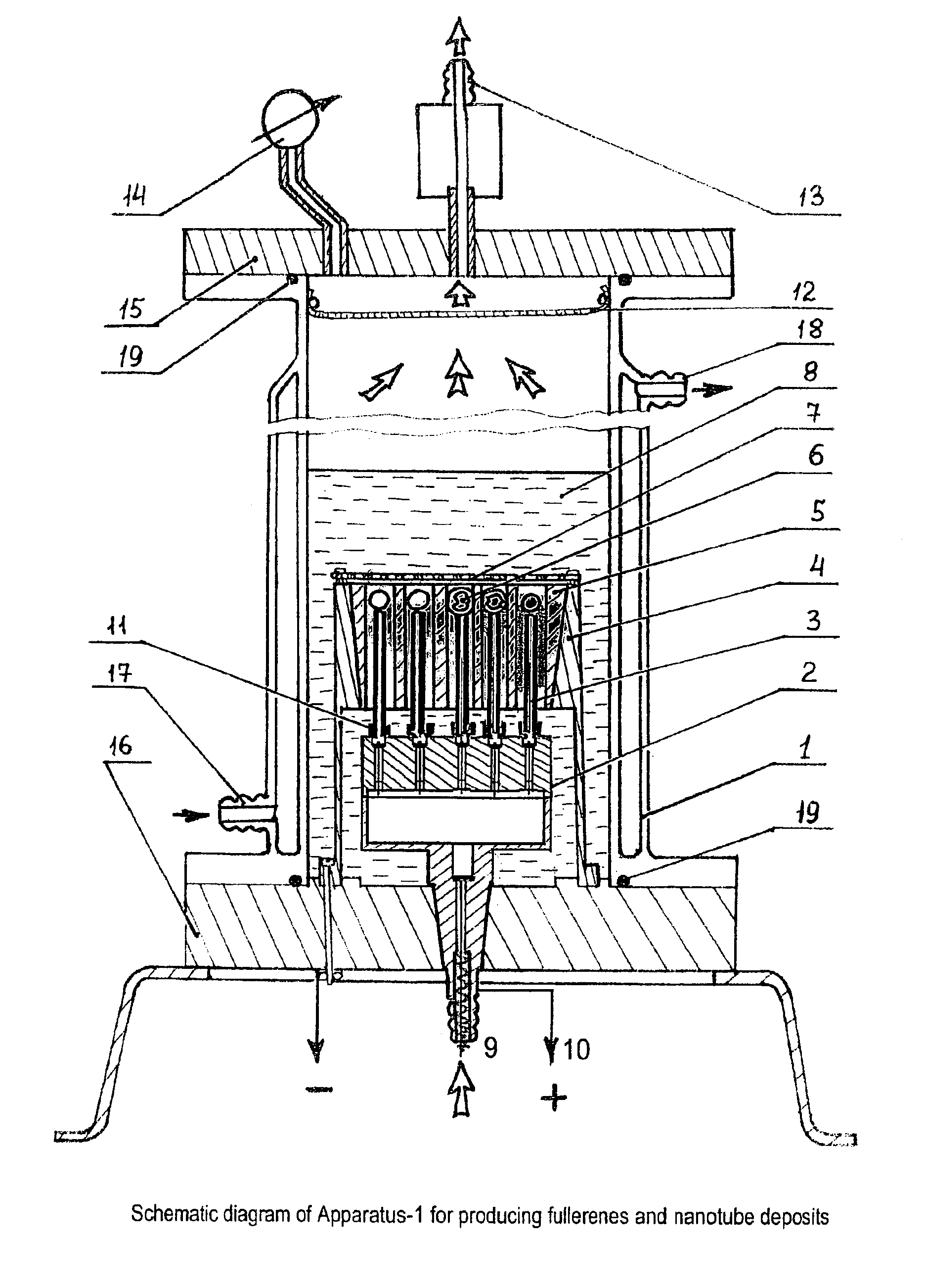
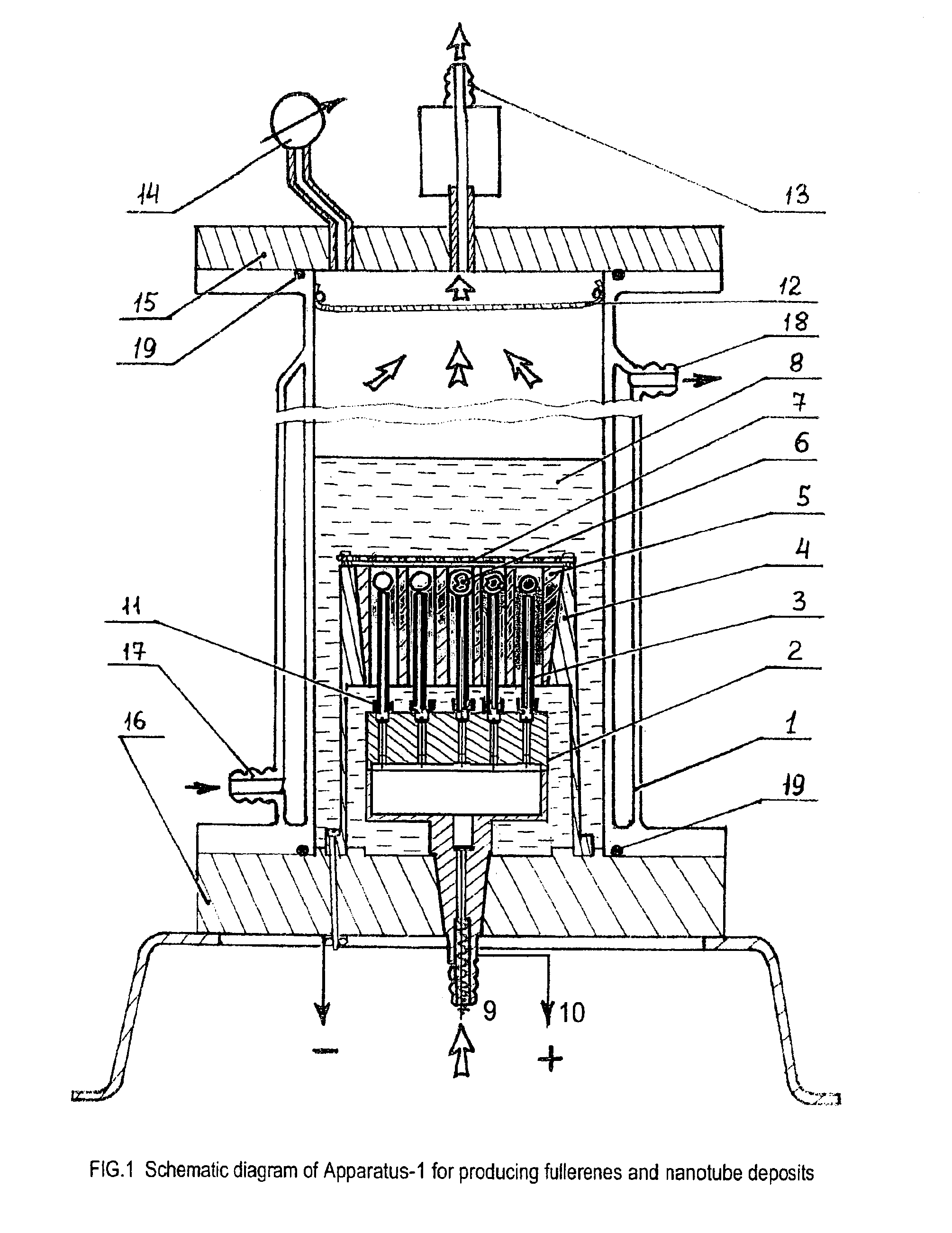
[0116]The following example relates to FIGS. 1 to 8 and to the first aspect of the present invention defined above.

[0117]An individual cell of the device for producing fullerenes includes a hermetically sealed body 1, in which a holder 2 of the electrodes A (3) and a holder 4 of the electrode B (5), and spherical graphite contactors 6 are situated above the electrodes A below a metallic grid 7. This arrangement is immersed in a hydrocarbon liquid 8 and is connected to a valve 9 for flowing a buffer gas, and to a standard AC power supply 10 typically used for welding (three phase voltage, 53V, 50 Hz). Cylindrical graphite pipes 3 (electrodes A) with a smaller diameter are installed in holder 2 by using cylindrical ceramic insulators 11 and are connected to the holder using safety wires. The pipes are axially installed inside a vertical cylindrical opening of a graphite matrix 5 (electrode B).

[0118]FIG. 1 shows a design of the apparatus with 19 pairs of the electrodes / contactors verti...


PUM

PropertyMeasurementUnit
pressureaaaaaaaaaa
pressureaaaaaaaaaa
pressureaaaaaaaaaa

Abstract

A fullerene / nanotubes mixture is produced during a periodical pulsed auto-regulated action of the electric current arc-discharge in the multi-component hydrocarbon medium with limited fullerenes' solubility, besides, the action is continued until the medium dissolves C60. Higher fullerenes absorbed by the ultra-thin graphite particles are separated from C60 dissolved in the liquid medium by sedimentation, whereas the carbon nanotubes are separated from the ultra-thin graphite particles by treating with a boiling concentrated HN03 acid and by low speed centrifuging / acid mixture until the black sediment of the ultra-thin graphite particles is precipitated to the bottom. The periodically pulsed auto-regulated regime of the electric-current arc-discharge is performed by contact breaking an electric circuit due to lifting spherical contactors by gaseous products released during the action and by switching the circuit due to the contacts' going down under action of gravity.

Description

APPLICATION CROSS-REFERENCES[0001]This application is a continuation-in-part of PCT Application No. PCT / IB00 / 00406, filed 20 Mar. 2000, and which named the United States as a designated country. This application also claims priority of PCT Application No. PCT / IB99 / 00481, filed 23 Mar. 1999; Great Britain Application No. 0121554.0, filed 6 Sep. 2001; and Great Britain Application No. 0121558.1, filed 6 Sep. 2001.FIELD OF THE INVENTION[0002]The invention is related to chemical technologies, particularly to the field for the production of fullerenes and carbon nanotubes.BACKGROUND OF THE INVENTION[0003]Fullerenes and nanotubes are the most desirable materials for basic research in both chemistry and physics, as well as research in electronics, non-linear optics, chemical technologies, medicine, and others.[0004]The processes of producing new allotrope forms of carbon, fullerenes, nanotubes and nanoparticles (buckyonions) are based on the generation of a cool plasma of carbon clusters b...

Claims


Application Information

Patent Timeline
Patent Type & Authority Patents(United States)
IPC IPC(8): C01B31/00C01B31/02
CPCB82Y30/00B82Y40/00C01B31/0246C01B31/0213Y10S977/734C01B32/166C01B32/156C01B32/154
Inventor RYZHKOV, VLADISLAV ANDREEVITCH
Owner ROSSETER HLDG
Why Eureka
Try Eureka